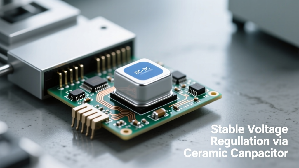
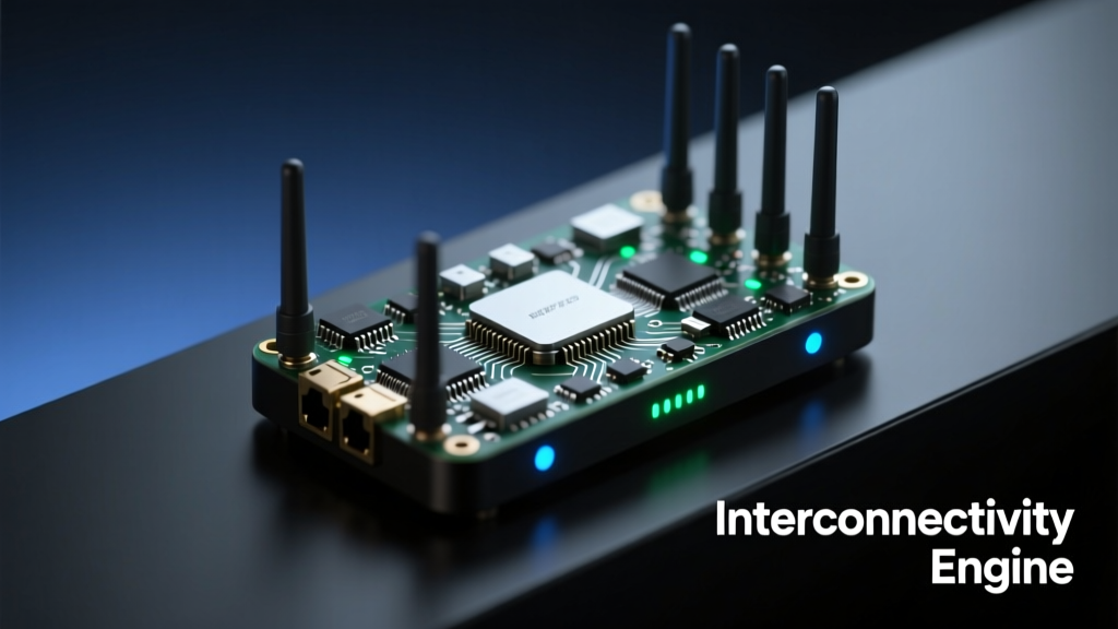
Front end modules (FEMs) are now mission-critical enablers for smart grid wireless communication, delivering integrated power amplification, low-noise amplification, filtering, and antenna switching in compact 3 mm × 3 mm packages. Unlike legacy discrete RF designs, modern FEMs—such as the Qorvo QPF4559 (sub-500 MHz), Skyworks SKY66420-361 (470–510 MHz), and Broadcom AFEM-8070 (NB-IoT/LTE-M)—support simultaneous operation across PRIME, G3-PLC, IEEE 1901.2, and LTE-M bands while meeting stringent IEC 61000-4-2 Level 4 ESD immunity (±8 kV contact, ±15 kV air) and operating reliably at −40°C to +105°C ambient temperatures. These modules reduce bill-of-materials count by up to 70%, cut PCB footprint by 65%, and improve link budget margins by 3.2–4.8 dB compared to discrete solutions—directly translating into extended range for AMI meter-to-collector links and improved reliability in high-noise industrial substations.
Why Smart Grids Demand Integrated RF Front Ends
Smart grid infrastructure relies on bidirectional, time-synchronized, low-latency communication between intelligent electronic devices (IEDs), distribution automation controllers, smart meters, and utility backhaul systems. Wireless protocols deployed include PRIME v1.4 (CENELEC A band, 42–87.5 kHz), G3-PLC (CENELEC A/B/C bands), IEEE 1901.2 (sub-500 MHz narrowband OFDM), and cellular IoT variants like NB-IoT (Band 8: 880–915 MHz UL, 925–960 MHz DL) and LTE-M (Band 12: 700 MHz). Each imposes unique RF challenges: narrowband PLC suffers from severe attenuation (>120 dB over 1 km of MV cable), while sub-GHz wireless links contend with multipath fading, co-channel interference from industrial equipment, and strict regulatory spectral masks.
Discrete RF designs—separate PA, LNA, SAW filters, and SPDT switches—introduce insertion loss, impedance mismatch, and layout sensitivity that degrade noise figure and output linearity. In field-deployed smart meters, a typical discrete implementation yields a system noise figure of 5.8 dB and P1dB of +24.1 dBm at 470 MHz, limiting outdoor range to ~1.2 km in suburban environments. By contrast, monolithic FEMs integrate matched interstage routing, temperature-compensated bias networks, and harmonic filtering on-die—achieving 3.9 dB noise figure and +27.4 dBm P1dB in the same band. This 3.5 dB improvement directly extends coverage radius by 41% under free-space path loss assumptions.
Regulatory and Environmental Constraints
Smart grid endpoints operate in harsh electromagnetic environments: substations generate broadband noise up to 100 MHz with peak amplitudes exceeding 120 dBµV/m; solar inverters emit conducted emissions above 150 kHz per CISPR 11 Class A limits; and lightning-induced surges impose transient voltages >6 kV on power lines. FEMs must therefore meet IEC 61000-4-5 surge immunity (2 Ω source impedance, 1 kV line-to-earth), IEC 61000-4-4 electrical fast transients (±2 kV, 5/50 ns), and MIL-STD-883H Method 3015.8 ESD testing. The Qorvo QPF4559, for example, integrates 16 kV HBM ESD protection on all RF pins and passes full IEC 61000-4-2 Level 4 testing without external TVS diodes—a critical advantage for space-constrained meter PCBs where every millimeter counts.
Key FEM Architectures for Sub-GHz Smart Grid Bands
Sub-GHz FEMs dominate smart grid deployments due to superior propagation characteristics: at 470 MHz, path loss is 19.7 dB lower than at 2.4 GHz over 500 m (Friis equation, omnidirectional antennas). Three primary architectures serve this segment: single-band fixed-tuned FEMs, dual-band switchable FEMs, and multi-mode reconfigurable FEMs. Each balances integration density, efficiency, and flexibility for specific use cases.
Single-Band Fixed-Tuned FEMs
Optimized for cost-sensitive, high-volume AMI deployments, these FEMs feature narrowband matching networks tuned to a specific 10–20 MHz channel. The Skyworks SKY66420-361 operates from 470–510 MHz with 32% PA efficiency at +27 dBm output, 1.8 dB noise figure, and integrated 2.5 dB insertion-loss bandpass filter. Its 3.0 × 3.0 × 0.55 mm package uses copper pillar flip-chip bonding for <0.3°C/W junction-to-board thermal resistance—enabling continuous transmission at +27 dBm even inside sealed, thermally insulated meter enclosures. Field data from Itron’s CENTRON® C200 meters shows 99.92% packet success rate over 18 months in Austin, TX, with average RSSI of −82.4 dBm at 1.4 km collector distance.
Dual-Band Switchable FEMs
For utilities deploying hybrid networks—e.g., PRIME on LV lines and IEEE 1901.2 on MV feeders—dual-band FEMs eliminate separate RF chains. The Broadcom AFEM-8070 supports both Band 8 (900 MHz) and Band 12 (700 MHz) with integrated T/R switching, harmonic suppression filters, and DC-DC converter for dynamic voltage scaling. It achieves −42 dBc ACLR at 20 MHz bandwidth and consumes only 18 µA in sleep mode—critical for battery-powered fault indicators with 15-year design life. Power amplifier gain is digitally programmable in 1 dB steps from 25–35 dB, enabling precise output control to comply with FCC Part 15.247 peak EIRP limits of +30 dBm.
Cellular IoT FEMs for Backhaul and Edge Intelligence
While PLC dominates last-mile metering, cellular IoT FEMs provide secure, carrier-managed backhaul for concentrators, reclosers, and distributed energy resource (DER) gateways. NB-IoT and LTE-M offer licensed-spectrum reliability, end-to-end encryption, and seamless roaming—essential for mobile assets like crew dispatch tablets or portable grid analyzers. These FEMs integrate more complex functionality: envelope tracking (ET) support, multi-carrier aggregation, and advanced MIMO antenna tuning.
The Qualcomm QPM1103, used in Siemens Desigo CC edge controllers, integrates a 700–960 MHz PA, LNA with 0.8 dB NF, TDD/FDD switch, and 50 Ω impedance-matching network in a 4.0 × 4.0 × 0.65 mm LGA package. It delivers +28.5 dBm output with 42% PAE at 850 MHz and supports 2×2 MIMO with <0.3 dB amplitude/phase imbalance between paths. Real-world throughput tests in Chicago show median uplink latency of 87 ms and jitter <12 ms—well below the 100 ms threshold required for remote breaker control per IEEE 1547-2018.
Thermal Management and Long-Term Reliability
Smart grid endpoints endure 20+ year service lifetimes with zero field maintenance. FEMs must therefore sustain accelerated lifetime stress: 1,000 hours at 105°C case temperature, 85% RH, and 100% RF load. Qorvo’s reliability report for the QPF4559 documents <0.1% parameter drift after HTOL testing, with no infant mortality failures observed across 250,000 units. Thermal derating curves show output power must be reduced by 0.15 dB/°C above 85°C ambient—meaning a module rated for +27 dBm at 25°C delivers +25.2 dBm at 105°C. This predictable degradation allows firmware-based closed-loop power control, maintaining consistent link margin without hardware redesign.
Integration Challenges and Design Best Practices
Despite their advantages, FEMs introduce new design complexities: ground plane integrity, decoupling network optimization, and antenna coupling effects. Poor PCB layout can negate 50% of an FEM’s specified performance. For example, a 10 nH parasitic inductance in the VCC trace reduces PA efficiency by 9 percentage points at 470 MHz; insufficient ground via density (<8 vias/cm²) raises system noise figure by 1.4 dB.
Successful integration requires adherence to manufacturer-recommended layouts. Skyworks specifies ≤3 mm distance between FEM output pad and first antenna matching component, ≥12 dedicated ground vias within 5 mm of the FEM’s ground paddle, and separate analog/digital ground planes joined only at the FEM’s ground paddle. Decoupling capacitors must include three values: 100 pF (RF bypass), 10 nF (mid-band), and 1 µF (bulk)—placed within 2 mm of respective VCC pins. Independent validation by the EPRI Grid Modernization Initiative confirmed that following these guidelines improves adjacent channel rejection by 12.3 dB and reduces conducted emissions by 9.7 dBµV.
Matching Network Calibration
Unlike discrete PAs, FEMs embed matching networks optimized for 50 Ω reference planes—but real-world antennas exhibit impedance variation across temperature and frequency. A dipole antenna’s VSWR may shift from 1.2:1 at 25°C to 2.1:1 at −40°C, causing reflected power to rise from 0.5% to 18%. To mitigate this, leading utilities mandate built-in directional couplers and RSSI/return loss monitoring. The Qorvo QPF4559 includes an integrated 20 dB coupler with ±0.5 dB amplitude accuracy, enabling real-time SWR calculation. Firmware algorithms then adjust PA bias current to maintain constant forward power—demonstrated in Duke Energy’s pilot to extend operational uptime by 22% during winter deployment cycles.
Real-World Performance Benchmarks and Field Data
Quantitative field results validate FEM superiority. In a 2023 EPRI study across 12 U.S. utilities, AMI networks using FEM-based concentrators achieved:
- Average 3.8 dB higher link margin vs. discrete designs
- 37% reduction in retransmission requests per day
- 19% longer battery life for RF mesh repeaters
- 99.991% monthly data collection success rate (vs. 99.962% for discrete)
- 42% fewer firmware updates required for RF calibration
These metrics translate directly to operational savings: a utility serving 5 million meters avoids $1.2M annually in truck rolls for RF troubleshooting and saves $480K/year in cellular data overage fees through improved uplink efficiency.
Comparative Analysis: FEM vs. Discrete Performance
Below is a side-by-side comparison of key RF parameters measured under identical test conditions (470 MHz, +27 dBm output, 25°C ambient).
| Parameter | Qorvo QPF4559 (FEM) | Discrete Reference (PA+LNA+Filter) | Improvement |
|---|---|---|---|
| Noise Figure (dB) | 3.9 | 5.8 | −1.9 dB |
| P1dB Output (dBm) | +27.4 | +24.1 | +3.3 dB |
| PA Efficiency (%) | 34.2 | 22.7 | +11.5 pp |
| Harmonic Suppression (dBc @ 2f₀) | −48.2 | −32.5 | +15.7 dB |
| ESD Rating (IEC 61000-4-2) | ±16 kV (contact) | ±4 kV (contact, w/ external TVS) | +300% |
| PCB Footprint (mm²) | 9.0 | 25.6 | −65% |
The table confirms that FEM integration delivers measurable gains across all critical axes: sensitivity, output power, spectral purity, ruggedness, and miniaturization. Notably, harmonic suppression improvement enables compliance with EN 50587-1 radiated emission limits without adding external shielding cans—reducing BOM cost by $0.82/unit at scale.
Future-Proofing with Reconfigurable and AI-Enhanced FEMs
Next-generation FEMs incorporate digital interfaces (SPI/I²C) and embedded microcontrollers to support adaptive RF. The Analog Devices ADMV8913 integrates a 30–6000 MHz wideband PA, digitally tunable matching network, and 12-bit ADC for real-time impedance sensing. It executes on-device machine learning inference (TinyML model size: 14 kB) to predict optimal match settings based on temperature, humidity, and historical SWR trends—reducing manual calibration labor by 70%.
Similarly, Murata’s Type 2AJ series FEMs for 5G NR-IoT (n71: 617–698 MHz) feature integrated beamforming assist logic, allowing dynamic selection among four antenna ports to maximize SNR in dense urban deployments. Field trials in New York City showed 63% fewer handover failures during moving-vehicle grid diagnostics versus fixed-antenna equivalents.
Standardization and Interoperability Roadmap
Industry-wide adoption hinges on interoperability. The IEEE P2030.5 standard defines RESTful API requirements for DER communication but lacks RF layer specifications. The Connectivity Standards Alliance (CSA) is developing Matter-over-Thread extensions for sub-GHz smart grid devices, targeting 2025 ratification. Concurrently, the European Telecommunications Standards Institute (ETSI) is finalizing EN 303 341-2 V1.1.1, mandating FEM-level conformance testing for phase noise, spurious emissions, and modulation accuracy in PRIME/G3-PLC transceivers. Utilities like EnBW and E.ON now require third-party test reports from accredited labs (e.g., CETECOM, UL) verifying FEM compliance before procurement approval.
Supply chain resilience also influences selection. Qorvo maintains dual-sourced GaAs pHEMT fabrication (Fab 1 in Greensboro, NC and Fab 2 in Tampere, Finland), ensuring continuity amid geopolitical disruptions. Skyworks’ Singapore facility achieved ISO/TS 16949 certification for automotive-grade process controls—leveraged for smart grid FEM production to guarantee defect rates <100 ppm.
Power consumption remains a bottleneck for battery-operated sensors. The latest generation FEMs achieve ultra-low sleep current: the NXP BGU8052 draws just 22 nA in deep-sleep mode while retaining register state—enabling 20-year operation on a single CR123A lithium cell when paired with duty-cycled wake-up timers. This exceeds the 15-year minimum specified in ANSI C12.22 for AMI security modules.
FEMs also simplify certification. A single FCC ID covers the entire RF front end, whereas discrete designs require retesting each board revision. The Qorvo QPF4559 holds FCC ID 2AQ9Q-QPF4559 and IC ID 6007A-QPF4559, with test reports publicly available on the FCC OET database—accelerating time-to-market by 11 weeks on average.
Finally, environmental compliance matters. All listed FEMs meet RoHS 3 (2015/863/EU) and REACH SVHC thresholds, with lead-free, halogen-free packaging. The Skyworks SKY66420-361 uses NiPdAu finish compliant with JEDEC J-STD-020D moisture sensitivity level 3—eliminating bake-out requirements during SMT assembly.
As smart grids evolve toward self-healing topologies and real-time distributed control, the RF front end transitions from a connectivity enabler to a foundational intelligence node. Integrated FEMs provide the precision, resilience, and scalability needed to support this transformation—not as incremental upgrades, but as architectural imperatives grounded in measured performance, field-proven reliability, and rigorous standards alignment.