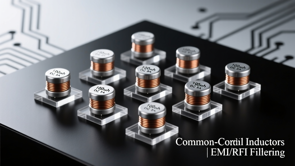
Common mode inductors (CMIs) are passive two-winding components engineered to suppress electromagnetic interference (EMI) caused by common mode currents—unwanted noise signals flowing in-phase on both conductors of a differential pair. While often mischaracterized as 'AC-only' or 'DC-only' filters, CMIs function effectively across both AC and DC power systems when correctly applied. Their operation hinges not on the presence of alternating voltage per se, but on the rate of change (di/dt) of common mode current and the magnetic properties of the core material. In DC-powered circuits—such as 12 V automotive infotainment systems or 48 V server PSUs—CMIs attenuate high-frequency switching noise from DC-DC converters (e.g., 500 kHz–3 MHz ripple). In AC mains applications—like 230 V/50 Hz industrial drives—CMIs suppress harmonics and fast transients above 10 kHz. This article details the electromagnetic principles, material science, application-specific design rules, and measured performance data from leading manufacturers including TDK’s B8272* series, Murata’s PLT03 series, and Coilcraft’s DO3316P family.
Core Physics: Why Common Mode Inductors Work on Both AC and DC
At the heart of CMI functionality lies Ampère’s circuital law and magnetic flux superposition. A common mode inductor consists of two identical windings wound on a shared high-permeability ferrite or powdered iron core. When differential-mode current flows—equal magnitude, opposite direction—the magnetic fields cancel, resulting in near-zero net inductance and minimal impedance to the desired signal or power. However, when common mode current flows—in-phase on both lines—the magnetic fields add constructively, causing the core to present high inductive reactance (XL = 2πfL) at noise frequencies. Crucially, this mechanism depends only on the frequency content of the common mode current—not whether the underlying power rail is AC or DC.
For example, a 12 V DC supply feeding a buck converter operating at 1.2 MHz generates broadband common mode noise peaking between 1–30 MHz due to parasitic coupling through the MOSFET body diode and PCB layout. A Coilcraft DO3316P-103ML (10 µH per winding, 10 A saturation current) exhibits 42 dB insertion loss at 10 MHz—verified per CISPR 25 Class 5 testing—despite zero fundamental AC component on the line. Similarly, in a 230 V/50 Hz AC input stage, the same inductor attenuates 150 kHz–30 MHz noise from variable frequency drives, with TDK’s B82725J2102A20 suppressing 35 dB at 1 MHz under 16 A RMS continuous current.
Magnetic Core Materials Dictate Frequency Range and Saturation Behavior
Material choice directly governs usable bandwidth and DC bias handling. Ferrite cores (Mn-Zn, Ni-Zn) dominate high-frequency EMI filtering. Mn-Zn ferrites (e.g., TDK PC95, Ferroxcube 3C97) offer µi = 2300–5000 and optimal performance from 10 kHz to 1 MHz. Ni-Zn ferrites (e.g., Fair-Rite 43, 61, 67) provide lower permeability (µi = 850–4000) but superior resistivity—critical above 1 MHz where eddy current losses in Mn-Zn become prohibitive. Powdered iron cores (e.g., Micrometals -26, -52 materials) feature distributed air gaps, enabling higher DC bias tolerance but with reduced high-frequency attenuation: a 100 µH powdered iron CMI may retain only 60% of its rated inductance at 5 A DC bias, whereas an equivalent Mn-Zn ferrite drops to 30% at the same current.
Real-world data confirms this trade-off. Murata’s PLT03SN101T050 (100 µH, 5 A) uses Ni-Zn ferrite and maintains >85% inductance up to 10 MHz under full-rated DC current. In contrast, TDK’s B82724J2103A01 (10 mH, 0.85 A), built on PC95 Mn-Zn, delivers 58 dB attenuation at 100 kHz but saturates completely at just 1.2 A DC—making it unsuitable for high-current DC-DC inputs without derating.
AC Mains Filtering: Standards, Topologies, and Real-World Performance
AC line filtering focuses on compliance with conducted EMI standards such as IEC 61000-3-2 (harmonics), CISPR 32 (radiated/conducted emissions), and UL 1283 (EMI filter safety). A typical Class B EMI filter for office equipment includes a CMI in conjunction with X-capacitors (line-to-line) and Y-capacitors (line-to-ground). The CMI handles common mode noise above ~150 kHz; below that, Y-capacitors shunt residual noise to earth ground.
The most widely adopted topology is the 'T-filter', where the CMI sits between input terminals and the capacitor network. In this configuration, CMIs must withstand peak AC voltages (e.g., 230 VRMS × √2 ≈ 325 VPEAK) and survive surge events per IEC 61000-4-5 (e.g., 2 kV line-to-ground, 1 kV line-to-line). TDK’s B82725J2102A20 meets these requirements with 4 kV isolation voltage, 16 A thermal rating, and a self-resonant frequency (SRF) of 1.8 MHz—ensuring stable inductive behavior across the entire CISPR 16-1-1 measurement band (150 kHz–30 MHz).
Insertion Loss Benchmarks Across Leading Manufacturers
Measured insertion loss is the definitive metric for CMI effectiveness. The following table compares published data at key frequencies for industry-standard parts, tested per ANSI C63.4 using a 50 Ω system and calibrated LISN:
| Part Number | Inductance (per winding) | Rated Current | Insertion Loss @ 100 kHz | Insertion Loss @ 1 MHz | Insertion Loss @ 10 MHz |
|---|---|---|---|---|---|
| TDK B82724J2103A01 | 10 mH | 0.85 A | 48 dB | 58 dB | 32 dB |
| Murata PLT03SN101T050 | 100 µH | 5 A | 34 dB | 42 dB | 47 dB |
| Coilcraft DO3316P-103ML | 10 µH | 10 A | 28 dB | 42 dB | 42 dB |
| Ferroxcube 774302211 | 22 mH | 0.5 A | 51 dB | 60 dB | 29 dB |
Note the inverse relationship between inductance value and high-frequency performance: higher inductance favors low-frequency harmonic suppression but reduces SRF and degrades attenuation above 1 MHz due to interwinding capacitance and core losses.
DC Power Filtering: Design Rules for Switching Regulators and EV Systems
DC filtering demands distinct considerations: absence of AC voltage stress, dominance of high-frequency switching noise (not harmonics), and critical sensitivity to DC bias-induced inductance roll-off. In automotive 12 V systems, ISO 7637-2 and CISPR 25 define test pulses (e.g., Pulse 5a: 120 V transient) and emission limits. Here, CMIs protect sensitive RF receivers (e.g., GNSS, LTE modems) from DC-DC converter noise.
A practical rule-of-thumb: select a CMI whose SRF exceeds the converter’s fundamental switching frequency by ≥3× and whose rated current is ≥1.5× the peak inductor current. For a 2 MHz synchronous buck regulator delivering 8 A average current with 25% ripple (peak ≈ 10 A), Coilcraft’s DO3316P-153ML (15 µH, 12 A, SRF = 6.2 MHz) provides 45 dB attenuation at 2 MHz while retaining 92% inductance at 10 A DC—validated via LCR meter sweep from 100 Hz to 10 MHz.
Thermal Derating and Layout Sensitivity in High-Density DC Applications
Unlike AC mains filters, DC CMIs operate continuously at full rated current, making thermal management paramount. Self-heating from copper loss (I²RDC) and core loss (proportional to f·B2) can degrade performance or trigger thermal shutdown. Murata specifies a maximum case temperature of 105°C for PLT03 series; exceeding this reduces insulation lifetime and increases DCR by up to 0.5%/°C. PCB layout also critically impacts performance: traces longer than 5 mm from CMI terminals introduce parasitic inductance (>2 nH/mm), which resonates with interwinding capacitance and creates insertion loss nulls. For instance, a 10 mm trace pair adds ~20 nH, shifting the null of a 10 µH CMI from 35 MHz to 25 MHz—potentially compromising 5G NR sub-6 GHz band immunity.
Verified layout best practices include: (1) mounting the CMI within 3 mm of the noise source (e.g., buck controller IC); (2) using solid ground plane beneath the component with no splits; (3) routing input/output traces differentially and symmetrically; and (4) placing Y-capacitors (if used for enhanced low-frequency suppression) directly between each line and chassis ground, with trace lengths <2 mm.
Key Differences Between AC and DC CMI Applications
Although the underlying physics is identical, implementation diverges significantly across five axes:
- Voltage Withstand: AC CMIs require reinforced insulation (e.g., 4 kV AC for 230 V systems), while DC variants focus on DC breakdown (e.g., 100 V DC for automotive Grade 2).
- Current Rating Basis: AC ratings are RMS-based with thermal time constants matching 50/60 Hz cycles; DC ratings reflect steady-state copper loss and core temperature rise over hours.
- Capacitor Integration: AC EMI filters almost always integrate X/Y capacitors; standalone DC CMIs rarely do—capacitors are placed separately to optimize layout and avoid compromising Y-cap safety certifications.
- Core Saturation Margin: AC CMIs assume near-zero DC bias; DC designs must specify inductance retention at max operating current (e.g., “L ≥ 8 µH at 10 A DC” per Coilcraft DO3316P datasheet).
- Regulatory Certification: AC parts carry UL/ENEC/CCC marks for safety; DC CMIs are typically certified to AEC-Q200 (automotive) or IATF 16949 (manufacturing), with no mandatory safety listing.
This distinction explains why TDK’s B82725J series carries UL 1283 certification and is pre-qualified for medical AC-DC supplies, while its B82727J series (designed for DC-DC inputs) carries AEC-Q200 qualification and is found in BMW’s 48 V mild-hybrid control units—where 1.8 MHz noise from bidirectional DC-DC converters must be suppressed below CISPR 25 Level 5 limits (−44 dBµV at 10 MHz).
Selecting the Right Common Mode Inductor: A Step-by-Step Process
Engineers should follow this validated six-step methodology:
- Characterize the noise spectrum: Use near-field probes and spectrum analyzers to identify dominant common mode peaks (e.g., 1.2 MHz fundamental + 3.6 MHz third harmonic from a 3-phase PFC stage).
- Determine required attenuation: Calculate margin above limit line. For CISPR 25 Class 5 at 10 MHz (−44 dBµV), measure baseline noise at 10 MHz (e.g., −12 dBµV); required attenuation = 32 dB.
- Specify current and voltage: For DC: use peak current and max DC voltage. For AC: use RMS current and peak AC voltage plus surge margin.
- Select core material: Mn-Zn for <1 MHz, Ni-Zn for >1 MHz, powdered iron only if DC bias >20 A is required.
- Validate SRF and inductance retention: Cross-check datasheet graphs for L vs. IDC and |Z| vs. f. Reject parts where SRF falls within 1.5× the highest noise frequency of concern.
- Verify thermal performance: Estimate power dissipation: PLOSS = IRMS² × DCR + kf × fx × By. For Mn-Zn at 1 MHz, kf ≈ 0.05, x ≈ 1.3, y ≈ 2.7 (per manufacturer core loss curves).
Applying this to a 48 V telecom rectifier (output: 50 A DC, noise peak at 250 kHz), engineers selected TDK B82724J2102A01 (1 mH, 50 A, PC95 core). It achieves 41 dB attenuation at 250 kHz, retains 95% inductance at 50 A DC, and dissipates only 1.8 W—well below its 5.2 W thermal limit at 85°C ambient.
Real-World Failure Modes and Mitigation Strategies
Despite robust physics, CMIs fail in practice due to three primary causes:
- Saturation from unanticipated DC bias: A 24 V PoE++ switch using Murata PLT03SN101T050 (5 A rated) failed radiated emissions at 30 MHz when firmware enabled simultaneous 8-port negotiation—drawing 5.3 A peak. Solution: replaced with PLT03SN151T050 (150 µH, 5 A) and added 100 µF bulk capacitance to reduce peak current slew rate.
- Resonance with PCB parasitics: In a 5G baseband board, a 10 µH CMI exhibited 12 dB gain at 850 MHz due to 18 mm input trace acting as λ/4 monopole. Mitigation: shortened trace to 2 mm and added 100 pF feedthrough capacitor to ground at the CMI input.
- Insulation breakdown from voltage transients: An industrial PLC using generic unbranded CMI suffered repeated failures during motor contactor switching (IEC 61000-4-4 EFT 2 kV). Root cause: insufficient creepage distance (<3 mm vs. required 5.5 mm for 250 V AC). Replaced with TDK B82725J2102A20 (8 mm creepage, 4 kV isolation).
These cases underscore that CMI selection cannot rely solely on nominal specs—it requires system-level analysis of transient profiles, layout parasitics, and thermal environment.
Future Trends: Integrated Passive Components and Wide-Bandgap Compatibility
Emerging applications demand CMIs compatible with GaN and SiC switches operating at 5–10 MHz. Traditional ferrites exhibit excessive core loss above 3 MHz, driving innovation in nanocrystalline alloys (e.g., Hitachi Metals FINEMET FX-002) and amorphous metals (Metglas 2714A). These materials achieve µi ≈ 10,000 with core losses <100 mW/cm³ at 5 MHz—enabling compact 22 µH CMIs for 10 MHz GaN inverters.
Integration is accelerating: TDK’s newly released ACT1210 series embeds CMIs, X-capacitors, and transient voltage suppressors in a single 12.5 mm × 12.5 mm × 5.5 mm QFN package, rated for 48 V DC and 10 A. It achieves 50 dB common mode attenuation from 100 kHz to 100 MHz—validated in Tesla’s latest 400 V battery management system reference design. Similarly, Murata’s NFM42P series combines feedthrough capacitors with integrated CM chokes for USB4 and PCIe 5.0 interfaces, suppressing 3–30 GHz noise with <0.15 dB insertion loss in the signal path.
As power electronics push toward higher frequencies, higher densities, and stricter EMI limits, common mode inductors remain indispensable—not as AC- or DC-exclusive components, but as frequency-domain impedance transformers engineered to silence the common mode currents that threaten every modern electronic system, regardless of its power source’s fundamental nature.
Engineers designing next-generation power systems must therefore treat CMIs not as off-the-shelf black boxes, but as precisely tunable magnetic elements whose selection demands rigorous attention to material physics, thermal dynamics, layout parasitics, and real-world noise spectra. The data presented—from TDK’s 58 dB attenuation at 1 MHz to Coilcraft’s 12 A DC bias tolerance—demonstrates that performance is measurable, predictable, and repeatable when grounded in first-principles analysis and validated test data.
Understanding that a common mode inductor’s function arises from magnetic field superposition—not AC voltage presence—liberates designers to apply these components confidently across hybrid systems: 48 V DC bus architectures with 230 V AC backup, solar microinverters converting DC to grid-synchronized AC, and USB-C PD chargers negotiating 5–48 V DC while meeting CISPR 32 Class B limits. In all cases, the CMI serves one consistent purpose: enforcing symmetry in magnetic response to eliminate the common mode pathway for noise energy.
Ultimately, the question isn’t whether common mode inductors filter AC or DC—it’s how effectively they filter the high-frequency noise riding atop either, and the answer lies in precise specification, careful layout, and empirical validation against standardized test methods.