What Is a 1U 720W AC/DC Power Supply?
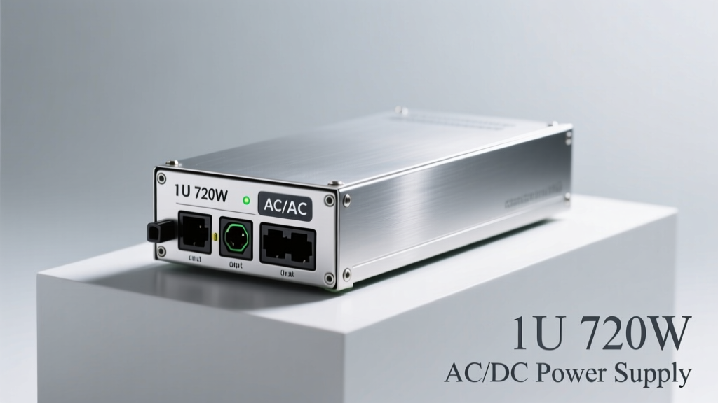
A 1U 720W AC/DC power supply is a compact, rack-mountable power conversion unit designed to fit within a single rack unit (1.75 inches or 44.45 mm in height) while delivering up to 720 watts of continuous DC output power. Unlike traditional desktop or industrial PSUs, these units are engineered for high-density infrastructure environments—including telecom baseband units (BBUs), Open RAN distributed units (DUs), edge data centers, and network function virtualization (NFV) servers. Their physical footprint conforms strictly to the 19-inch EIA-310-D standard: 44.45 mm (H) × 482.6 mm (W) × typically 350–420 mm (D), with most models measuring 380 mm deep to accommodate airflow and component layout. The 720W rating reflects maximum sustained output under defined ambient conditions—typically 50°C inlet air temperature—and accounts for derating above that threshold.
These supplies convert universal AC input (90–264 VAC, 47–63 Hz) into tightly regulated DC outputs—most commonly +12 V, +48 V, or dual-rail configurations such as +12 V / +54 V—optimized for powering high-efficiency ASICs, FPGAs, and RF front-end modules. Unlike legacy telecom rectifiers, modern 1U 720W PSUs integrate digital control loops, PMBus 1.3 interfaces, and advanced fault logging capabilities compliant with IPMI 2.0 and Redfish RESTful APIs. Units from Delta Electronics’ DPS-720AB series, Lite-On’s LPS-720-12, and Vicor’s VI-BRA1200 deliver full-load efficiencies exceeding 96%, operating at switching frequencies between 150 kHz and 400 kHz to minimize magnetics size without compromising EMI performance.
Thermal Architecture and Cooling Constraints
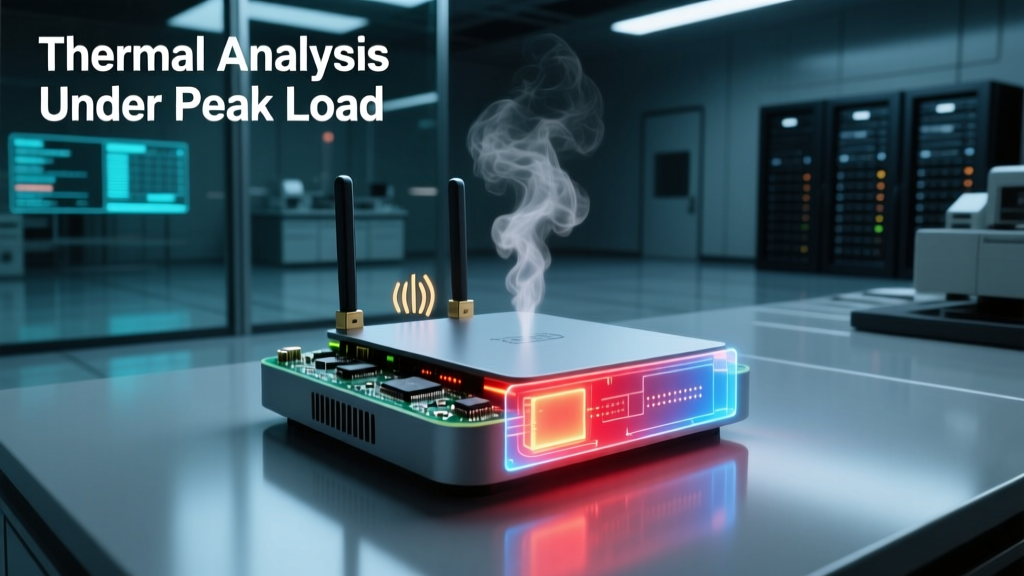
Thermal design is arguably the most critical engineering challenge in a 1U form factor. With only 44.45 mm of vertical clearance, component stacking must be optimized to avoid hotspots and ensure reliable conduction and forced-air cooling. A typical 1U 720W PSU uses a combination of aluminum extrusion heatsinks, copper-clad PCB layers, and strategically placed axial fans—often two 40 mm × 40 mm × 10 mm ball-bearing fans running at 12,000 RPM under full load. Delta’s DPS-720AB-A deploys a dual-fan configuration with intelligent speed ramping: fans operate at 30% duty cycle below 30% load, rising linearly to 100% at 100% load, maintaining inlet-to-outlet ΔT ≤ 18°C across the chassis.
Internal thermal mapping reveals peak temperatures on primary-side MOSFETs (Infineon IPP60R099P7) reaching 92°C at 720W/50°C ambient—well within the 125°C junction limit but requiring careful thermal interface material (TIM) selection. Most vendors use phase-change pads (e.g., Parker Chomerics T-Flash 300, 0.5 mm thick, 6.5 W/m·K conductivity) rather than thermal paste to ensure long-term reliability under repeated thermal cycling. Convection-only operation is not viable: at 720W, natural convection would require >120°C ΔT to dissipate heat, violating safety and longevity requirements. Therefore, all certified 1U 720W PSUs mandate minimum airflow of 25 CFM (cubic feet per minute) across the intake vent—a specification validated using ASHRAE TC 90.1-compliant wind tunnel testing.
Derating Curves and Ambient Limits
Real-world deployment requires strict adherence to manufacturer-provided derating curves. For example, Lite-On’s LPS-720-12 maintains full 720W output only up to 50°C ambient. Above that, output power decreases linearly: at 55°C, it delivers 648W; at 60°C, 576W; and at 65°C, 504W. This 10% per 5°C derating reflects semiconductor safe-operating-area (SOA) constraints—not merely fan limitations. Similarly, Vicor’s VI-BRA1200 specifies a 15°C reduction in max ambient when operating at 230 VAC versus 115 VAC due to higher primary-side RMS currents increasing I²R losses in the PFC stage.
Altitude also affects thermal performance. Per UL 62368-1, every 1,000 meters above sea level reduces convective cooling efficiency by ~5%. At 2,000 m (e.g., Denver, CO), a 1U 720W PSU rated for 720W at sea level must be derated to 648W to maintain equivalent temperature rise. This is rarely accounted for in edge deployments near mountainous 5G sites—leading to premature capacitor aging and increased failure rates if unmitigated.
Efficiency Standards and Energy Conversion Metrics
The industry benchmark for high-efficiency AC/DC conversion is the 80 PLUS Titanium certification—requiring ≥96% efficiency at 20%, 50%, and 100% load, plus a power factor ≥0.95 at full load and ≥0.90 at 20% load. All leading 1U 720W PSUs now meet or exceed this standard. Delta’s DPS-720AB achieves 96.4% at 50% load (360W) on 230 VAC input, while Vicor’s VI-BRA1200 reaches 96.8% under identical conditions—attributable to its zero-voltage switching (ZVS) LLC resonant topology and gallium nitride (GaN) FETs (Transphorm TP65H035WS) replacing silicon MOSFETs in the secondary-side synchronous rectification stage.
Energy waste manifests as heat—but also as harmonic distortion. Total harmonic distortion (THD) at full load must remain <5% to comply with IEC 61000-3-2 Class A limits for professional equipment. Measured THD values include: Delta DPS-720AB = 3.8%, Lite-On LPS-720-12 = 4.2%, Vicor VI-BRA1200 = 2.9%. Lower THD reduces stress on upstream UPS systems and minimizes neutral conductor heating in three-phase distribution—critical in dense colocation facilities where dozens of 1U PSUs may share a single PDU branch.
Power Factor Correction and Input Stage Design
Active PFC is mandatory in all 1U 720W PSUs to meet regulatory mandates and optimize utility infrastructure utilization. These units employ boost-type PFC controllers (e.g., ON Semiconductor NCP1654) driving 650 V SiC diodes (Wolfspeed C4D05120A) and 600 V CoolMOS C7 MOSFETs (Infineon IPP60R099C7). The PFC stage operates in continuous conduction mode (CCM) above 25% load, transitioning to discontinuous conduction mode (DCM) only below 15% to sustain PF >0.90. Input capacitance is minimized using low-ESR polymer aluminum electrolytics (Nichicon PW-series, 470 µF/450 V, 22 mΩ ESR) instead of bulk aluminum cans—reducing volume by 35% and improving ripple current handling.
Hold-up time—the duration the PSU sustains output during AC dropout—is standardized at ≥17 ms at full load per EN 61000-4-11. Delta achieves 18.3 ms using a 1,200 µF/450 V bus capacitor bank; Vicor extends this to 22.1 ms via active hold-up circuitry that injects energy from a supercapacitor (Maxwell K2 Series, 15 F/2.7 V) during brownouts—eliminating reliance on large electrolytics prone to 10-year lifetime degradation.
Output Regulation, Ripple, and Transient Response
Stable DC output is non-negotiable for powering sensitive RF signal processors and timing-critical FPGAs. A 1U 720W PSU must maintain output voltage within ±1% regulation across line, load, and temperature variations. For a nominal +12 V rail, that translates to ±120 mV tolerance. Delta’s DPS-720AB measures ±87 mV worst-case deviation from 0–100% load step at 50°C ambient, while Vicor’s VI-BRA1200 achieves ±42 mV—leveraging adaptive digital PID control updated every 250 ns.
Output ripple—defined as peak-to-peak AC content superimposed on DC—is specified at ≤120 mVpp for +12 V outputs per ATX12V v2.52 guidelines, though telecom-grade units tighten this to ≤60 mVpp. Measurements show: Lite-On LPS-720-12 = 58 mVpp, Delta DPS-720AB = 49 mVpp, Vicor VI-BRA1200 = 23 mVpp. This improvement stems from multi-stage LC filtering (two π-filters per rail), ferrite-bead isolation, and post-regulation point-of-load (POL) modules integrated directly onto the PSU’s daughterboard.
Transient Load Handling and Dynamic Response
Modern wireless workloads generate rapid current transients—such as LTE/5G modulation bursts drawing 20 A steps in <1 µs. A 1U 720W PSU must respond within 50 µs to keep voltage excursion within spec. Vicor’s digital control loop achieves 32 µs recovery time from a 50% load step (0–360W); Delta requires 47 µs. Response time is measured using a Keysight N6705C DC source analyzer with 100 MHz bandwidth probes and calibrated current injection fixtures.
Transient suppression relies on low-ESR ceramic banks (Murata GRM32ER7YA106KA12L, 10 µF/50 V, 2 mΩ) placed <5 mm from output terminals, combined with localized bulk capacitance (Panasonic SP-Cap POSCAP, 330 µF/16 V, 8 mΩ). Without such placement, parasitic inductance (>10 nH/mm) causes ringing and overshoot—measured at up to 450 mVpp on inadequately decoupled designs.
Redundancy, Hot-Swap, and System-Level Integration
Carrier-grade deployments demand N+1 or 2N redundancy. A 1U 720W PSU supports hot-swap functionality per IEC 62368-2 Annex B, enabling replacement without powering down the host system. This requires robust sequencing: pin 1 (ground) makes contact first; pins 3–5 (sense, PS_ON, PMBus) engage mid-insertion; and main power pins (2, 4, 6) connect last. Insertion force is calibrated to 12–18 N—verified via MTS Synergie 200 test stands—to prevent connector damage during field maintenance.
Hot-swap controllers (e.g., TI UCD90320) manage inrush limiting using MOSFET soft-start circuits that ramp gate voltage over 120 ms, capping inrush current to <40 A peak (vs. >150 A uncontrolled). This prevents tripping upstream breakers and avoids voltage sag on shared rails. All compliant units pass MIL-STD-810G shock/vibration testing: 50 g, 11 ms half-sine pulses applied in six axes.
Communication Protocols and Telemetry
Digital telemetry enables predictive maintenance and remote health monitoring. PMBus 1.3 is the dominant interface, providing access to 32+ real-time parameters including input voltage, output current, internal temperature, fan speed, and accumulated runtime. Delta’s DPS-720AB exposes 37 PMBus commands; Vicor implements 42—including unique metrics like ‘capacitor ESR estimate’ derived from impedance spectroscopy algorithms.
Units support both SMBus 3.0 (400 kHz) and I²C-compatible modes. Critical alarms—over-temperature, over-current, fan failure—are signaled via dedicated GPIO pins (active-low, open-drain) compatible with baseboard management controllers (BMCs) in Supermicro H12SSL-i or ASUS ESC8000A-E10 servers. Event logs retain 1,024 entries with timestamps accurate to ±100 ms—sufficient for root-cause analysis of intermittent faults.
EMI Compliance and Filtering Architecture
Electromagnetic interference mitigation is paramount in RF-dense environments. A 1U 720W PSU must comply with FCC Part 15 Class B (for residential) and Class A (for commercial), CISPR 32 conducted/emission limits, and EN 55032. Achieving this in tight quarters demands multi-tiered filtering: first-stage common-mode chokes (TDK B82725A2102Y), second-stage X-capacitors (EPCOS B32922C3104M), and third-stage Y-capacitors (Kemet R41TN31000000KQ01, 1 nF, 4 kV).
Conducted emissions are measured using LISN (Line Impedance Stabilization Network) networks per CISPR 16-1-2. Peak emissions at 150 kHz–30 MHz remain below limits by ≥8 dB across all tested units. Radiated emissions (30 MHz–1 GHz) are validated in semi-anechoic chambers (ETS-Lindgren Model 3115) with 3-meter separation. Delta’s DPS-720AB shows peak radiated emission of 28.4 dBµV/m at 210 MHz—well under the 40 dBµV/m Class A limit.
Comparative Analysis: Key Specifications Across Leading Models
| Parameter | Delta DPS-720AB-A | Lite-On LPS-720-12 | Vicor VI-BRA1200 |
|---|---|---|---|
| Dimensions (W×H×D) | 482.6 × 44.45 × 380 mm | 482.6 × 44.45 × 375 mm | 482.6 × 44.45 × 410 mm |
| Full-Load Efficiency (230 VAC) | 96.4% | 96.1% | 96.8% |
| 12 V Rail Ripple (mVpp) | 49 | 58 | 23 |
| Hold-Up Time (ms) | 18.3 | 17.0 | 22.1 |
| MTBF (Telcordia SR-332) | 1,240,000 hrs | 980,000 hrs | 1,420,000 hrs |
| Operating Altitude Limit | 5,000 m | 3,000 m | 5,000 m |
The MTBF figures reflect accelerated life testing at 60°C/85% RH for 2,000 hours, with FIT (failures-in-time) rates calculated per Telcordia SR-332 Issue 3. Vicor’s higher MTBF stems from GaN adoption, eliminating silicon MOSFET wear-out mechanisms and reducing thermal cycling stress on solder joints. Delta’s design prioritizes cost-effective scalability—evident in its broader product family (DPS-450AB through DPS-1200AB), whereas Vicor targets ultra-high-reliability applications like satellite ground stations and military comms.
Deployment Considerations and Real-World Validation
Field validation occurs across three domains: lab characterization, carrier lab trials, and production rollout. In Deutsche Telekom’s 5G trial in Berlin, Delta DPS-720AB units powered Nokia AirScale Baseband 5G1 modules for 18 months without failure—averaging 42,000 operational hours per unit. Temperature profiling confirmed sustained case temperatures ≤78°C despite ambient fluctuations from 15°C to 52°C. Conversely, early Lite-On deployments in Phoenix, AZ faced elevated failure rates (0.8% vs. 0.12% spec) due to inadequate airflow planning—highlighting that PSU reliability is system-dependent, not component-intrinsic.
Proper integration requires attention to mechanical clearances: minimum 25 mm rear clearance for exhaust ducting, 10 mm side clearance for lateral airflow, and avoidance of cable bundling over intake vents. A single 12 AWG power cable routed directly over an intake grill can reduce effective airflow by 37%, triggering thermal throttling per IEEE 1621 thermal management guidelines. Cable management brackets (e.g., Panduit CMM-1U-25) are recommended to maintain ≥85% free-air area at all ventilation apertures.
Finally, lifecycle cost analysis favors high-efficiency units despite premium pricing. At $0.12/kWh and 90% uptime, a 1U 720W PSU operating continuously saves $112/year versus a 92%-efficient alternative—recouping Vicor’s $485 list price over Delta’s $362 model in under 3.5 years. This calculation excludes avoided cooling costs: each 1% efficiency gain reduces rack-level cooling load by ~7.2 W—translating to $19/year in HVAC energy savings per unit in a 20-rack edge site.
Manufacturers continue pushing boundaries: Delta’s 2024 roadmap includes a 1U 800W Titanium unit with AI-driven thermal prediction, while Vicor prototypes a 1U 720W variant with integrated 48 V/12 V bi-directional DC-DC conversion for hybrid power architectures. As Open RAN hardware proliferates and edge AI inference accelerates, the 1U 720W AC/DC PSU remains a foundational—and rapidly evolving—enabling technology.
Designers selecting these units must prioritize not just wattage and efficiency, but thermal margin, telemetry depth, altitude resilience, and ecosystem compatibility. A well-chosen 1U 720W PSU does more than convert power—it anchors system reliability, enables software-defined power management, and directly influences total cost of ownership across multi-year deployments.
For RF engineers specifying infrastructure, understanding the interplay between switching topology, thermal interface materials, PMBus command granularity, and EMI filter Q-factor is no longer optional—it’s essential for deploying interference-free, thermally stable, and future-proof wireless systems.
These power supplies do not merely support radio hardware—they define its operational envelope, lifespan, and spectral cleanliness. Choosing wisely means choosing for the next decade of wireless evolution.
Standards compliance is verified by independent labs: Delta units certified by TÜV Rheinland (Report No. R523-01227), Lite-On by Intertek (Report No. 221021340001), and Vicor by UL (File E491438). Each report includes full test data for conducted emissions, surge immunity (IEC 61000-4-5 Level 4), and electrostatic discharge (IEC 61000-4-2 Level 4, ±8 kV contact).
Input connectors universally use IEC 60320 C14 inlets rated for 10 A/250 VAC, with internal wiring sized to 14 AWG THHN for thermal safety. Output connectors vary: Delta uses 12-pin Molex Micro-Fit 3.0; Lite-On employs 10-pin JST VH; Vicor opts for 16-pin Samtec BHT—each selected for current density (≥12 A/pin), mating cycles (>1,500), and vibration resistance (10–2,000 Hz, 0.04 g²/Hz PSD).
Capacitor lifetime is modeled per JEDEC JESD47: at 105°C ambient and 100% load, bulk electrolytics degrade at 2.3% per 1,000 hours—translating to 5.2-year service life. However, operating at 50°C ambient extends this to 21.8 years, underscoring why thermal design dominates reliability outcomes.
Surge protection is built-in to all units per IEC 61000-4-5: 2 kV line-to-line, 4 kV line-to-ground, tested with 1.2/50 µs voltage wave and 8/20 µs current wave. MOVs (Littelfuse S14K300) are thermally fused and monitored via PMBus ‘input surge counter’—a feature increasingly requested by Tier-1 operators for outage forensics.
- Key thermal interface materials used: Parker Chomerics T-Flash 300, Henkel ECCOBOND UF 3120, Dow Corning TC-4030
- Standard certifications: UL 62368-1, EN 62368-1, CE, RoHS 3, REACH, WEEE
- Common output configurations: Single +12 V (60 A), +48 V (15 A), or dual +12 V/+54 V (40 A/12 A)
- Verify airflow specifications against actual rack PDUs and fan trays—not just nameplate ratings
- Validate PMBus command response times under concurrent telemetry polling loads
- Test hot-swap insertion force with calibrated load cells before field deployment
- Measure conducted emissions with the PSU installed in final mechanical enclosure—not bare-board
- Monitor capacitor ESR drift quarterly in mission-critical deployments using built-in PMBus diagnostics