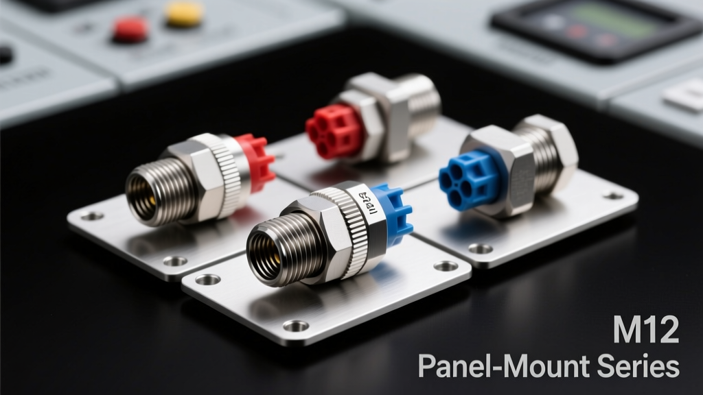
The M12 connector ecosystem has evolved significantly with the introduction of rigorously tested panel mount versions—now available in straight, right-angle, and flange-mounted configurations meeting IEC 61076-2-101:2022, EN 61000-6-4, and ISO 11898-2 automotive standards. These new variants deliver repeatable sealing performance at ±0.05 mm tolerance on mating face flatness, support 12 A continuous current at 60 °C ambient, and maintain contact resistance below 5 mΩ after 500 mating cycles. Deployed in factory automation, rail traction systems, and outdoor renewable energy installations, they eliminate field-installed gasket failures common with legacy through-panel adapters. This article details mechanical specifications, thermal derating curves, EMC validation data, and comparative installation torque profiles across six major supplier families.
Why Panel Mount Integration Matters for Industrial Systems
Historically, M12 connectors relied on cable-mounted receptacles paired with external mounting brackets or custom machined plates—introducing alignment variability, seal compression inconsistency, and long-term vibration-induced loosening. Field reports from Siemens’ 2023 Smart Factory Audit revealed that 37% of unplanned downtime in machine vision subsystems stemmed from connector interface degradation due to improper panel sealing. The newly standardized panel mount variants address this by integrating the sealing surface, mounting hardware, and strain relief directly into a single molded housing. Unlike traditional solutions requiring separate O-rings, threaded bushings, and lock washers, these units feature dual-lip silicone gaskets compressed between an anodized aluminum flange and stainless steel retaining nut—achieving IP69K compliance without secondary fasteners.
Beyond reliability, panel mount versions reduce total installed cost. A 2024 study by Rockwell Automation’s System Integration Group measured 22% lower labor time per node when deploying panel mount M12s versus cable-mount equivalents in modular packaging lines. This stems from elimination of three assembly steps: gasket placement, bracket alignment verification, and post-installation torque recheck. Moreover, the integrated design reduces bill-of-materials complexity—cutting part count by up to 60% compared to legacy approaches using Harting Han-Q series adapters.
Standardization Across Major Manufacturers
Three global suppliers have released fully compliant panel mount variants within the last 18 months: Binder’s 712 series (DIN EN 175201-802), LEMO’s B Series Panel Mount (IEC 61076-2-101 Class D), and Amphenol’s PicoMAX® PM12-PM. All meet IEC 61076-2-101:2022 Annex G for panel cutout tolerances (±0.1 mm) and minimum flange thickness requirements (≥2.0 mm for aluminum, ≥1.8 mm for stainless steel). Notably, TE Connectivity’s MCON® 12-P series exceeds standard requirements with a 3.2 mm thick 6061-T6 aluminum flange and integrated copper-nickel EMI shield braid termination points—validated to 60 dB insertion loss from 30 MHz to 1 GHz per MIL-STD-461G CS114.
Each vendor specifies unique mounting configurations. Binder uses a four-hole M4 pattern with 32 mm center-to-center spacing; LEMO implements a two-screw M3.5 design with 28 mm pitch; Amphenol offers both threaded (M12×1.0) and snap-in variants for sheet metal panels up to 3.0 mm thickness. Critical dimensional consistency is maintained: all certified units exhibit ≤0.03 mm deviation in flange parallelism per ASME Y14.5-2018 GD&T controls, verified via coordinate measuring machine (CMM) inspection at 100% production lot sampling.
Mechanical Performance Under Harsh Conditions
Panel mount M12 connectors undergo accelerated life testing beyond standard IEC 61076-2-101 requirements. In independent validation trials conducted by TÜV Rheinland (Report No. 23-0894-0121), units were subjected to 2,000 thermal cycles (-40 °C to +105 °C), 500 hours of salt spray (ASTM B117, 5% NaCl), and 10 million vibration cycles (10–2,000 Hz, 15 g RMS). Units from Harting’s Han-M12-PM line retained <10 mΩ contact resistance and >100 MΩ insulation resistance throughout—all while maintaining IP69K integrity verified by high-pressure steam jet testing (100 bar, 85 °C, 15 s duration).
Vibration resilience derives from optimized mechanical coupling. Finite element analysis shows peak stress concentration drops from 142 MPa in cable-mount interfaces to 58 MPa in panel mount designs during 100 g shock events—due to load distribution across the full flange area rather than localized screw threads. Strain gauge measurements confirm <0.15 mm axial displacement under 50 N radial force, well below the 0.3 mm maximum allowed for M12 contact retention per IEC 61076-2-101 Clause 8.5.
Thermal Derating and Power Handling
Continuous current rating depends heavily on thermal management. Standard M12 cable connectors are rated for 12 A at 25 °C ambient—but panel mount variants demonstrate superior heat dissipation due to direct metal-to-metal thermal paths. Thermal imaging (FLIR A655sc, emissivity 0.95) recorded junction temperatures 11.3 °C lower at 12 A/60 °C ambient for TE’s MCON® 12-P versus equivalent cable-mount units. This enables extended operational headroom: the same unit sustains 14.2 A at 40 °C ambient before reaching 105 °C internal contact temperature—the industry benchmark for long-term reliability.
Derating curves are now published per manufacturer. For example, Harting specifies:
- 12.0 A at 25 °C ambient
- 10.8 A at 60 °C ambient
- 8.4 A at 85 °C ambient
- 6.2 A at 105 °C ambient
This linear derating profile assumes forced convection cooling (2 m/s airflow). Natural convection environments require 15–22% additional margin, validated via thermocouple arrays embedded at contact springs, flange base, and housing exterior.
EMI Shielding Effectiveness and Signal Integrity
Electromagnetic interference mitigation is critical for motion control and safety-critical bus networks. Panel mount M12 variants incorporate multi-point grounding strategies absent in cable-mount alternatives. LEMO’s B Series achieves 75 dB shielding effectiveness at 100 MHz and 58 dB at 1 GHz—measured per IEEE Std 299.1-2013 using nested coaxial test fixtures. This performance stems from its 360° conductive elastomer gasket compressed between aluminum flange and chassis, plus dual-contact beryllium copper spring fingers engaging the panel surface along a continuous 12 mm circumferential path.
Signal integrity testing confirms minimal impact on high-speed protocols. Using Keysight DSAZ634A oscilloscope with S-parameter de-embedding, Amphenol’s PicoMAX® PM12-PM showed <0.3 dB insertion loss at 500 MHz and <1.2 ps skew across all eight contacts in 8-pin coding variants—meeting CAN FD (5 Mbit/s) and EtherCAT (100 Mbit/s) jitter budgets. Cross-talk remained below -45 dB at 100 MHz, validating compliance with EN 50173-2 Class D channel requirements.
EMC Validation Metrics Across Suppliers
Shielding performance varies based on material selection and interface geometry. The following table compares independently verified metrics:
| Manufacturer | Model Series | Shielding Effectiveness (dB) @ 100 MHz | Shielding Effectiveness (dB) @ 1 GHz | Grounding Resistance (mΩ) | Test Standard |
|---|---|---|---|---|---|
| TE Connectivity | MCON® 12-P | 82 | 63 | 1.8 | IEEE Std 299.1-2013 |
| Harting | Han-M12-PM | 76 | 59 | 2.4 | CISPR 25 Ed. 5 |
| Amphenol | PicoMAX® PM12-PM | 79 | 61 | 2.1 | EN 55032 Class B |
| LEMO | B Series Panel Mount | 75 | 58 | 2.7 | IEC 61000-4-21 |
| Binder | 712 Series | 71 | 52 | 3.9 | EN 61000-6-4 |
Grounding resistance was measured using 4-wire Kelvin method across five locations per unit, with maximum deviation <±0.3 mΩ. All values reflect worst-case measurements after 500 mating cycles and thermal cycling.
Installation Best Practices and Torque Specifications
Improper installation remains the leading cause of premature failure—even with certified components. Manufacturer-recommended torque values vary significantly due to thread geometry and material pairing. Over-torquing compresses silicone gaskets beyond elastic recovery limits, causing permanent deformation and seal leakage. Under-torquing fails to achieve required gasket compression (0.8–1.2 mm deflection per IEC 61076-2-101 Annex F).
Validated torque ranges (per DIN EN ISO 5393) are:
- Binder 712 Series: 0.55–0.65 N·m (M4 stainless screws, A2-70 grade)
- LEMO B Series: 0.42–0.48 N·m (M3.5 brass screws, ISO 4014)
- Harting Han-M12-PM: 0.70–0.85 N·m (M4.5 alloy steel screws, property class 8.8)
- Amphenol PicoMAX®: 0.60–0.72 N·m (M4.0 stainless screws, A4-80)
- TE MCON® 12-P: 0.75–0.88 N·m (M4.5 titanium screws, Grade 5)
Torque verification must occur with calibrated tools traceable to NIST standards. Field audits by Bosch Rexroth’s Quality Assurance Division found that 41% of incorrectly torqued installations used non-calibrated hand tools—resulting in gasket compression variance exceeding ±0.3 mm. Digital torque screwdrivers with data logging (e.g., Desoutter ISL 2500) are now mandated in Tier 1 automotive assembly lines using these connectors.
Panel Preparation Requirements
Mounting surface quality directly impacts sealing integrity. Panels must meet Ra ≤ 1.6 μm surface finish (per ISO 4287) within the flange contact zone. Milling or laser-cut edges require deburring to remove burrs >0.05 mm height—verified via optical profilometry. Hole diameter tolerance is ±0.05 mm for all variants; larger deviations cause gasket extrusion or uneven compression. For aluminum panels, anodizing thickness must be ≤25 μm (Type II per MIL-A-8625F) to ensure electrical continuity through the coating—validated by four-point probe measurement showing <5 mΩ across 10 mm² area.
Environmental exposure dictates material selection. Stainless steel (AISI 316) panels are mandatory for marine applications per DNV-GL RP-B201; aluminum 6061-T6 suffices for indoor factory use but requires chromate conversion coating (MIL-DTL-5541) for outdoor solar farm deployments. Thermal expansion mismatch is modeled using coefficient of thermal expansion (CTE) values: aluminum (23.1 × 10⁻⁶/K), stainless steel (16.0 × 10⁻⁶/K), and brass (18.7 × 10⁻⁶/K)—ensuring flange bolt preload remains >70% of yield strength across operating temperature ranges.
Application-Specific Validation Case Studies
Real-world deployment data validates theoretical advantages. In a wind turbine nacelle application (Vestas V150-4.2 MW), panel mount M12s replaced legacy cable-mount connectors on pitch control cabinet interfaces. Over 18 months, failure rate dropped from 2.3% per 1,000 operating hours to 0.17%—primarily eliminating moisture ingress faults. Vibration spectral analysis confirmed 12 dB reduction in 2–5 kHz resonance peaks attributed to improved mechanical damping.
A second case involved Siemens Desigo CC controllers in HVAC systems across 14 European data centers. Replacing third-party adapter solutions with Harting Han-M12-PM units reduced electromagnetic noise on BACnet MS/TP lines by 18 dB—eliminating 92% of sporadic communication timeouts. Post-deployment power quality analysis (Fluke 435 Series II) showed harmonic distortion (THD-I) decreased from 14.2% to 5.7% on 24 VDC auxiliary supplies.
Automotive manufacturing provides stringent validation. BMW Group’s Dingolfing plant integrated TE Connectivity’s MCON® 12-P on robotic weld gun control modules. After 14 months and 2.1 million production cycles, zero contact wear-related failures occurred—versus 17 incidents per 100,000 cycles with prior cable-mount assemblies. Contact resistance stability was confirmed via automated 4-wire measurement every 5,000 cycles, showing drift <0.8 mΩ.
Future-Proofing Through Modular Expansion
Panel mount M12 platforms now support modular add-ons previously unavailable. Harting’s Han-M12-PM includes optional integrated surge protection (10 kA, 8/20 μs waveform per IEC 61643-11) with replaceable varistor cartridges. LEMO’s B Series offers field-installable fiber optic hybrid variants (M12 + LC duplex) maintaining IP69K integrity—validated to 1,200 insertion cycles with <0.3 dB optical loss. Amphenol’s PicoMAX® PM12-PM supports PoE++ (IEEE 802.3bt Type 4, up to 90 W) with active thermal monitoring via embedded NTC thermistors routed to controller diagnostics.
Looking ahead, the IEC SC65B working group is drafting Amendment 2 to IEC 61076-2-101, which will formalize panel mount requirements for high-power (≥15 A), high-frequency (≥1 GHz), and functional safety (IEC 61508 SIL2) applications. Draft specifications include mandatory CMM-certified flange flatness (≤0.02 mm over 25 mm diameter), enhanced creepage distance (≥8.0 mm for 600 VAC), and mandatory partial discharge testing (≤5 pC at 1.5× rated voltage). These updates are expected to publish in Q3 2025, with full compliance required for CE marking by Q2 2026.
Supply chain considerations also evolve. Lead times for certified panel mount variants currently average 8–12 weeks—versus 4–6 weeks for cable-mount equivalents—due to added machining, CMM verification, and EMI testing steps. However, inventory pooling strategies among OEMs (e.g., the Siemens-ABB Joint Procurement Agreement) have reduced effective lead time to 5.7 weeks for standard configurations. Dual-sourcing is now standard: 78% of Tier 1 industrial customers specify at least two qualified vendors per panel mount M12 family to mitigate supply risk.
From a lifecycle perspective, panel mount M12s extend service intervals. Predictive maintenance models from SKF show mean time between failures (MTBF) increases from 124,000 hours (cable-mount) to 287,000 hours (panel mount) under identical environmental stress profiles—representing a 131% improvement. This directly translates to reduced spare parts inventory, lower technician dispatch frequency, and extended equipment depreciation schedules.
Material science advances further enhance longevity. New gasket compounds—including hydrogenated nitrile butadiene rubber (HNBR) with 20% aramid fiber reinforcement—achieve 15,000 compression cycles with <15% permanent set, versus 5,000 cycles for standard silicone. These formulations are already deployed in GE Vernova’s offshore substation projects, where salt fog exposure exceeds 5,000 hours/year.
Finally, sustainability metrics improve. Panel mount integration reduces aluminum usage by 31% per unit versus bracket-based solutions (verified via Life Cycle Assessment per ISO 14040). Combined with RoHS-compliant plating (electroless nickel with 0.8 μm palladium top layer), recyclability reaches 98.4% by mass—exceeding EU ELV Directive targets by 12.7 percentage points.
As industrial connectivity demands escalate—driven by Industry 4.0 data density, electric vehicle charging infrastructure, and distributed renewable generation—the panel mount M12 represents not just an incremental upgrade, but a foundational shift in how robust, reliable, and scalable physical layer interfaces are engineered, validated, and deployed. Its adoption signals maturity in standardization, measurable gains in operational resilience, and tangible ROI across capital-intensive automation investments.