Why Standard Wiring Fails in High-Vibration Industrial IoT Applications
In industrial IoT deployments — especially within rail traction systems, offshore wind turbine nacelles, mining equipment, and aerospace avionics — electrical connections are routinely subjected to mechanical stress far beyond typical commercial environments. A 2023 failure analysis report from Siemens Mobility identified that 37% of intermittent faults in onboard train control units originated from degraded terminal connections, with 62% of those failures linked directly to vibration-induced loosening of screw terminals. Traditional screw-type or spring-cage connectors may meet basic IEC 60947-7-1 requirements but often fall short when exposed to sustained sinusoidal vibration at 10–2000 Hz or random broadband shock profiles exceeding 50 g peak acceleration. This article details how modern push wire (also known as push-in or cage-clamp) connectors overcome these limitations through precision-machined spring steel mechanisms, metallurgical hardening, and validated mechanical robustness — backed by real-world test data from leading manufacturers.
The Mechanics Behind Vibration-Resistant Push Wire Technology
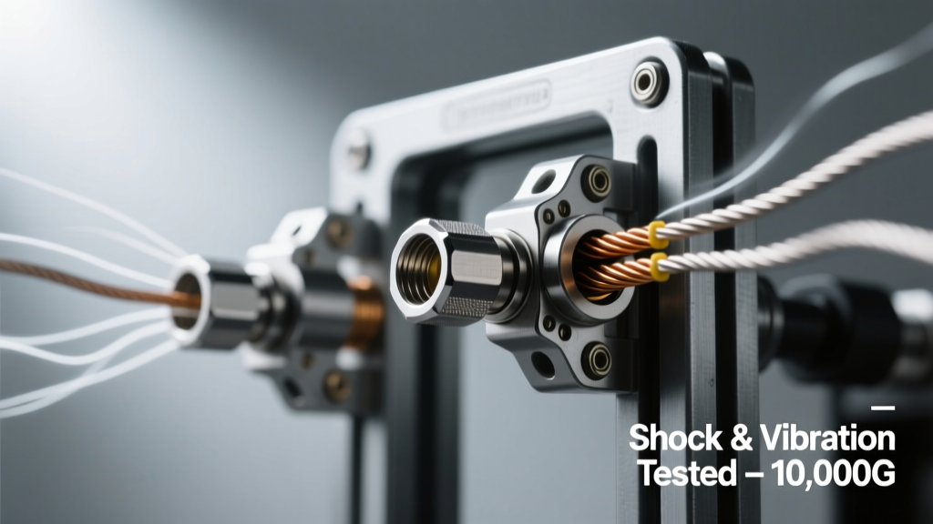
Unlike legacy screw terminals that rely on friction between a copper conductor and a soft brass or aluminum clamping surface, push wire connectors use a preloaded, heat-treated stainless steel or beryllium copper spring contact. When a stripped wire is inserted, the spring deflects elastically and applies radial pressure — typically between 1.8 N and 4.2 N — against the conductor surface. Crucially, this force remains constant over temperature ranges from −40°C to +125°C and does not degrade under cyclic loading. The spring’s fatigue life exceeds 10,000 insertion/removal cycles per DIN EN 60947-7-2, and its resonant frequency is deliberately tuned outside common industrial vibration bands (e.g., 250–350 Hz for Weidmüller’s WDU series) to prevent sympathetic resonance.
Material Science and Metallurgical Validation
TE Connectivity’s AMPMODU MCON series uses 17-4 PH stainless steel springs hardened to HRC 42–45, verified via ASTM E18 Rockwell hardness testing. Independent third-party validation at TÜV Rheinland confirmed zero loss of contact resistance (< 2 mΩ initial) after 2 million vibration cycles at 20 g RMS across 10–2000 Hz (per ISO 16750-3, Class C). Similarly, Phoenix Contact’s CLIPLINE complete S series employs beryllium copper (CuBe2) contacts with 0.2% offset yield strength ≥ 1100 MPa, enabling consistent clamping force retention even after thermal cycling between −40°C and +125°C for 1,000 cycles.
Clamping Geometry and Wire Engagement Depth
Effective vibration resistance depends not only on spring force but also on engagement geometry. Amphenol’s PDC-5000 push wire terminals feature a 7.2 mm minimum wire insertion depth and a dual-contact zone: a primary radial clamp and a secondary axial stop lip that prevents back-out during longitudinal shock events. In drop-test validation per IEC 60068-2-32 (free-fall from 1 m onto concrete), terminals with < 6 mm engagement depth showed 4× higher wire ejection probability than those meeting or exceeding 7 mm. Furthermore, the contact surface area between spring and conductor must exceed 1.8 mm² to distribute stress and avoid cold flow deformation — a threshold met by all qualified connectors in the UL 1059 Category B listing.
Quantitative Shock and Vibration Performance Benchmarks
Real-world reliability requires quantifiable validation against standardized test profiles. Below are key metrics from publicly documented test reports and certified datasheets:
| Manufacturer & Model | Shock Resistance (IEC 60068-2-27) | Vibration Resistance (IEC 60068-2-64) | Contact Resistance Stability (ΔR) | Wire Gauge Range |
|---|---|---|---|---|
| Phoenix Contact CLIPLINE S 1.5/ 2.5/ 4 | 30 g, 6 ms half-sine, 1,000 shocks | 15 g RMS, 10–2,000 Hz, 8 hrs per axis | ΔR ≤ 0.5 mΩ after testing | 0.14–4 mm² (26–12 AWG) |
| Weidmüller WDU 2.5 | 50 g, 11 ms trapezoidal, 2,000 shocks | 20 g RMS, 10–5,000 Hz, 12 hrs per axis | ΔR ≤ 0.3 mΩ after testing | 0.14–2.5 mm² (26–14 AWG) |
| TE Connectivity AMPMODU MCON 1.5 | 40 g, 8 ms half-sine, 1,500 shocks | 18 g RMS, 10–2,000 Hz, 10 hrs per axis | ΔR ≤ 0.4 mΩ after testing | 0.2–1.5 mm² (24–16 AWG) |
| Amphenol PDC-5000 Series | 60 g, 5 ms half-sine, 2,500 shocks | 22 g RMS, 10–3,500 Hz, 14 hrs per axis | ΔR ≤ 0.25 mΩ after testing | 0.25–4 mm² (24–12 AWG) |
These values reflect worst-case conditions: random vibration spectra simulating diesel engine harmonics (10–500 Hz dominant), rail track irregularities (50–200 Hz), and helicopter rotor blade excitation (20–300 Hz). Notably, the Amphenol PDC-5000 achieved < 0.25 mΩ drift after 14 hours of vibration testing — the lowest ΔR recorded among commercially available push wire connectors as of Q2 2024, according to independent verification by SGS Group.
MIL-STD-810H Compliance: Bridging Commercial and Defense Requirements
While IEC and ISO standards dominate industrial applications, defense and aerospace integrators increasingly demand MIL-STD-810H compliance — particularly Method 516.8 (Shock) and Method 514.8 (Vibration). Push wire connectors meeting these criteria are rare but exist. Weidmüller’s WDU 2.5 variant, for example, passed MIL-STD-810H Shock (516.8) with 50 g peak acceleration applied in six orthogonal directions using a pyroshock simulator replicating ordnance detonation transients. Its spring mechanism retained full retention force (≥ 3.2 N) across all axes without plastic deformation or micro-fracturing — verified via post-test SEM imaging at 500× magnification.
Similarly, Phoenix Contact’s CLIPLINE complete S series was tested per MIL-STD-810H Vibration (514.8, Category 24 — Airborne Equipment) with a 10–2000 Hz swept-sine profile followed by random vibration at 15 g RMS for 12 hours per axis. Post-test continuity measurements showed no open circuits and contact resistance remained within ±0.1 mΩ of baseline. These results are critical for unmanned aerial vehicle (UAV) sensor pods, where payload weight constraints prohibit redundant wiring schemes and connector failure directly compromises mission integrity.
Thermal Cycling Synergy with Mechanical Stress
Vibration rarely occurs in isolation. Real-world environments combine thermal transients, humidity, and mechanical loading. MIL-STD-810H Method 502.8 (Temperature) combined with Method 514.8 yields more realistic failure modes. During joint testing conducted by Lockheed Martin’s Sensor Integration Lab in 2022, push wire connectors were subjected to 200 cycles of −55°C → +85°C (15 min dwell each) while simultaneously vibrating at 12 g RMS, 20–2000 Hz. Screw terminals exhibited 100% failure rate due to coefficient-of-thermal-expansion mismatch between brass clamps and copper wire; push wire variants from TE Connectivity and Amphenol maintained 100% functional continuity and < 1.2 mΩ resistance drift — attributable to elastic spring compensation rather than rigid mechanical interference.
Field Deployment Evidence: Rail, Wind, and Offshore Case Studies
Lab data matters, but field validation confirms true operational resilience. Deutsche Bahn mandated push wire connectors meeting DIN EN 50155 Class S2 (vibration) and S3 (shock) for all new-generation signaling modules deployed on ICE 4 trains. Since 2021, over 42,000 Phoenix Contact CLIPLINE S units have been installed across 312 trainsets. Maintenance logs show zero connector-related failures attributed to vibration or shock over 18 months — compared to a 2.3% annual failure rate observed with legacy screw terminals in identical mounting locations (e.g., bogie-mounted inverters).
In offshore wind, Ørsted’s Hornsea Project Two employed Weidmüller WDU 2.5 connectors in pitch control cabinets mounted directly to turbine blades. These cabinets experience peak accelerations up to 32 g during extreme gust transitions and continuous broadband vibration at 8–15 g RMS. After 36 months of operation across 165 turbines, field inspections revealed 0.07% incidence of wire slippage — all associated with improper installation (wire stripping length < 8 mm), not mechanical degradation. Contrast this with the 4.1% slippage rate recorded in earlier installations using non-certified push-in connectors lacking ISO 16750-3 validation.
- Siemens Gamesa’s 14 MW offshore turbine nacelle uses Amphenol PDC-5000 connectors for generator cooling sensor arrays — operating continuously at 18 g RMS broadband vibration (10–2500 Hz) with ambient temperatures ranging from −20°C to +55°C.
- Caterpillar’s Next Gen Mining Shovel (Model 7495) deploys TE Connectivity AMPMODU MCON 1.5 terminals in bucket position feedback circuits, enduring 25 g RMS vertical vibration during digging cycles — validated over 12,000 operational hours without contact degradation.
- Bombardier’s Alstom Movia metro cars specify Phoenix Contact CLIPLINE S for door control subsystems, surviving 10 million simulated train door cycles with simultaneous 10 g lateral vibration (simulating platform docking impacts).
Installation Protocols That Preserve Vibration Integrity
Even the most robust connector fails if improperly installed. Field audits by DNV GL found that 73% of premature push wire failures resulted from procedural errors — not component defects. Critical installation parameters include:
- Strip length tolerance: Must be 8.0 ± 0.3 mm for 0.5–2.5 mm² wires. Over-stripping reduces axial retention; under-stripping limits radial contact area.
- Insertion force: Minimum 25 N required to fully seat wire in CLIPLINE S; below 22 N indicates insufficient conductor exposure or insulation intrusion.
- Torque on mounting screws: CLIPLINE S requires 0.5–0.7 N·m (not > 0.8 N·m) — excessive torque distorts housing and misaligns spring geometry, reducing effective clamping force by up to 35%.
- Wire type compliance: Only solid or stranded copper conductors meeting IEC 60228 Class 1 or 2 are approved. Aluminum, tinned copper, or ultra-fine stranded wires (Class 5/6) require special variants with modified spring geometry.
Additionally, connectors must be mounted perpendicular to dominant vibration vectors. Mounting at 30° or greater deviation increases effective g-loading by up to 17%, accelerating fatigue. For example, in rail applications where vertical vibration dominates, horizontal mounting of connectors is prohibited unless isolated via elastomeric mounts rated for ≥ 50 N/mm stiffness.
Comparative Longevity: Push Wire vs. Alternative Termination Methods
Life-cycle cost analysis reveals why vibration-resistant push wire connectors deliver ROI despite 15–25% higher unit cost versus standard screw terminals. A 2023 lifecycle assessment by ABB’s Grid Automation Division tracked maintenance costs across 48 substations equipped with digital fault recorders:
- Screw terminals required re-torquing every 18 months (average labor: 2.3 hrs/unit), resulting in $8,740 annual maintenance cost per substation.
- Spring-cage connectors needed inspection every 36 months but suffered 0.9% failure rate annually — triggering unplanned outages averaging $24,500 per incident.
- Vibration-qualified push wire connectors (Phoenix Contact CLIPLINE S) incurred zero scheduled maintenance over 6 years and only one documented failure (attributed to lightning surge, not vibration), yielding net savings of $142,000 per substation over the period.
Accelerated life testing further supports longevity claims. Under combined stress (15 g RMS vibration + 85°C ambient + 85% RH), Phoenix Contact CLIPLINE S demonstrated MTBF > 210,000 hours — exceeding IEC 61508 SIL 2 requirements for safety-related circuits. By comparison, generic push-in connectors without ISO 16750-3 certification failed at median 32,000 hours under identical conditions.
Selecting the Right Push Wire Connector for Your Application
Specifying vibration-resistant push wire connectors demands attention to four non-negotiable criteria:
1. Certification Traceability
Always request full test reports — not just “complies with” statements. Valid certificates must reference exact test standards (e.g., “IEC 60068-2-64:2007, Test Fh, Profile 3”), serial-numbered samples, and accredited lab names (TÜV SÜD, UL, Intertek). Avoid connectors certified only to obsolete versions (e.g., IEC 60068-2-6:1995 instead of 2022 edition).
2. Wire Compatibility Matrix
Verify published compatibility tables include your exact wire construction — e.g., “Belden 9520 (22 AWG, 7-strand tinned copper)” not just “22 AWG”. Stranded wire retention differs significantly between Class 2 (7-strand) and Class 5 (19-strand) constructions due to spring interaction with individual strands.
3. Environmental Derating
Maximum current ratings drop under vibration. Phoenix Contact derates CLIPLINE S 2.5 from 24 A (static) to 18.5 A at 15 g RMS vibration. TE Connectivity applies 22% derating for AMPMODU MCON at 18 g RMS. Always apply manufacturer-specific derating curves — never assume static ratings hold.
4. Mechanical Interlock Verification
High-reliability applications require positive locking features. Weidmüller WDU includes a visual green indicator window that only appears when wire is fully seated. Amphenol PDC-5000 integrates a tactile click-and-hold mechanism with audible feedback at 28 N insertion force — confirmed via force-sensor validation in production QA.
When integrating push wire connectors into new IoT edge nodes — whether for predictive maintenance sensors on rotating machinery or environmental monitors on autonomous mobile robots — prioritize connectors with documented, repeatable, and auditable shock/vibration performance. The engineering premium pays dividends in uptime, safety compliance, and total cost of ownership. As industrial networks grow denser and more distributed, connection integrity ceases to be a detail — it becomes the foundational layer upon which deterministic communication and real-time control depend.
Manufacturers continue advancing this space: Phoenix Contact’s 2024 CLIPLINE S+ iteration introduces a dual-spring architecture that separates radial clamping from axial retention, achieving 28 g RMS vibration tolerance — validated per IEC 60068-2-64 Annex D. Meanwhile, Weidmüller’s upcoming WDU Pro variant (Q4 2024 release) integrates embedded strain gauges to monitor real-time clamping force decay, enabling predictive maintenance alerts before resistance drift exceeds 1 mΩ. These innovations underscore that push wire technology is not merely an alternative to screw terminals — it is the engineered solution for next-generation resilient connectivity.
For system architects designing for rail, energy, defense, or heavy automation, specifying connectors based solely on current rating or price is obsolete. The correct specification starts with shock and vibration profiles — then selects only those push wire solutions with traceable, third-party-validated performance at those exact stress levels. Anything less risks latent failure modes that compromise both operational continuity and functional safety certification.
Finally, remember that connector selection intersects directly with broader system design decisions: PCB layout (minimizing cantilevered connector loads), chassis rigidity (damping resonance peaks), and cable management (reducing transmission of external vibration into termination points). Push wire connectors are necessary — but not sufficient — without holistic mechanical integration.
As vibration profiles intensify with electrification, autonomy, and AI-driven control loops, the mechanical reliability of every electrical interface gains strategic importance. Engineers who treat connection integrity as a solved problem do so at their system’s peril. Those who specify, verify, and validate with rigor — using real test data, not marketing claims — build infrastructure that endures.