Artemis II: The First Human Lunar Flyby in Over Five Decades
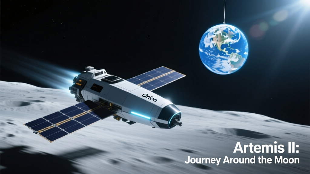
Artemis II is NASA’s historic return-to-the-Moon mission with astronauts aboard — slated for launch no earlier than September 2025. Unlike Artemis I (an uncrewed test flight), Artemis II will carry four astronauts — Commander Reid Wiseman, Pilot Victor Glover, Mission Specialist Christina Koch, and Mission Specialist Jeremy Hansen (CSA) — on a 10-day free-return trajectory that loops around the far side of the Moon at a minimum altitude of 13,420 km above the lunar surface. This mission validates human-rated deep-space systems under operational conditions, including life support, communications latency management, radiation monitoring, and autonomous navigation. Crucially, it does not land; instead, it serves as an integrated stress test for Orion’s environmental control and life support system (ECLSS), its European Service Module (ESM) built by Airbus Defence and Space, and the full-stack telemetry chain linking onboard sensors to NASA’s Deep Space Network (DSN) stations in Goldstone (California), Madrid (Spain), and Canberra (Australia).
The mission profile begins with a two-hour ascent aboard the Space Launch System (SLS) Block 1 rocket — the most powerful operational launch vehicle ever built, producing 8.8 million pounds of thrust at liftoff. Its core stage houses four RS-25 engines (flight-proven heritage from Space Shuttle orbiters, now upgraded with new engine controllers and updated avionics) and two five-segment solid rocket boosters supplied by Northrop Grumman. After Earth-orbit insertion and trans-lunar injection (TLI), Orion separates and begins its outbound coast, reaching a maximum distance of 394,000 km from Earth — farther than any human-rated spacecraft has traveled since Apollo 13 in 1970.
Orion’s Avionics and Sensor Architecture: Redundancy by Design
Orion’s command and data handling (C&DH) system is built around a fault-tolerant, radiation-hardened IBM PowerPC 750FX processor running VxWorks 6.9 real-time operating system — selected for deterministic timing and proven space heritage across multiple missions including Mars Science Laboratory. The C&DH unit interfaces with over 1,200 discrete sensors distributed across the crew module and ESM, grouped into functional subsystems: propulsion health, thermal management, pressure regulation, radiation dosimetry, inertial measurement, and cabin environmental monitoring.
Radiation Monitoring: From Silicon Detectors to Tissue-Equivalent Dosimeters
Deep-space radiation exposure remains one of the highest-risk variables for Artemis II. Orion carries three primary radiation sensing layers: (1) the Radiation Assessment Detector (RAD), developed by Southwest Research Institute and adapted from the Curiosity rover’s instrument suite, measuring galactic cosmic rays (GCRs) and solar particle events (SPEs) via silicon solid-state detectors and a cesium iodide scintillator; (2) the Hybrid Electronic Radiation Assessor (HERA), a NASA-developed active dosimeter using six silicon PIN diodes and thermoluminescent dosimeters (TLDs) calibrated to track absorbed dose (in grays) and equivalent dose (in sieverts); and (3) passive CRaTER-style tissue-equivalent plastic (TEP) stacks embedded in crew seats and wall panels, analyzed post-flight for cumulative linear energy transfer (LET) spectra.
During the lunar flyby phase, Orion will pass through the Van Allen belts in under 90 minutes — a window carefully timed to minimize exposure. Peak dose rates measured during Artemis I’s transit were 0.12 mSv/h in the inner belt and 0.03 mSv/h in the outer belt. For comparison, a typical chest CT scan delivers ~7 mSv; Artemis II’s projected total mission dose is capped at 25 mSv — well below NASA’s 600 mSv career limit for low-Earth-orbit astronauts but rigorously tracked minute-by-minute via HERA telemetry.
Inertial Navigation and Optical Tracking
Orion relies on a dual-redundant Inertial Measurement Unit (IMU) manufactured by Honeywell Aerospace — each containing three ring laser gyroscopes (RLGs) and three quartz accelerometers. These provide attitude, angular rate, and acceleration data at 100 Hz with drift stability better than 0.001°/h. Complementing inertial data are two Star Trackers (ASTRA units from Ball Aerospace) mounted on the service module’s aft bulkhead. Each ASTRA uses a 1024 × 1024-pixel CMOS detector with f/1.4 optics and a 12.5° field of view, achieving 2 arcsecond pointing accuracy by matching star patterns against a catalog of 5,000+ reference stars stored in non-volatile memory.
For optical navigation during the lunar far-side pass — where GPS is unavailable and radio signals are blocked — Orion employs the Optical Navigation Camera (ONC), a modified version of the Mars Reconnaissance Orbiter’s Context Camera (CTX). With a 2048 × 128-pixel frame-transfer CCD, 28 mm focal length lens, and 5.7° × 3.6° FOV, ONC captures sequential images of the Moon’s limb and surface craters every 30 seconds. Onboard flight software (running on Orion’s flight computers) performs centroiding, crater matching, and triangulation to determine position within ±5 km relative to the lunar ephemeris — critical for validating autonomous navigation algorithms ahead of Artemis III’s precision landing.
Thermal Management: Surviving Extreme Lunar Environments
Orion’s thermal control system (TCS) must manage heat loads ranging from −157°C in lunar eclipse shadow to +121°C in direct sunlight — a 278°C delta that challenges conventional radiators and insulation. The crew module uses multi-layer insulation (MLI) composed of 22 alternating layers of aluminized Kapton and Dacron scrim, developed by Saint-Gobain Performance Plastics. The ESM deploys a deployable radiator panel with titanium heat pipes filled with ammonia — manufactured by Airbus and tested to dissipate up to 1.8 kW of waste heat during peak operations.
Temperature sensors include over 200 platinum resistance thermometers (PRTs) calibrated to NIST Traceable Standards, spaced along critical plumbing lines, battery housings, and composite structural joints. Data from these sensors feed into Orion’s Thermal Control Subsystem (TCS) controller, which modulates coolant flow through the single-phase water-ammonia loop and adjusts radiator louver angles (actuated by SMA wire actuators from TiNi Aerospace) to maintain the crew cabin between 18–27°C and avionics between 10–40°C. During Artemis I, peak radiator outlet temperature reached 62.3°C at perigee; during lunar far-side passage, inlet temperatures dipped to −11.7°C — all within specification limits.
Communications Architecture: Bridging 400,000 km with Low-Latency Telemetry
Orion communicates via S-band (2.0–2.3 GHz) for voice, telemetry, and commanding, and Ka-band (26.5–40 GHz) for high-rate science and imagery downlink. The primary antenna is a steerable high-gain dish (0.85 m diameter) designed by Lockheed Martin and manufactured by L3Harris, capable of 50 Mbps downlink at lunar distance. Backup is provided by four low-gain antennas (LGAs) — two S-band and two UHF — ensuring omnidirectional coverage during ascent and contingency scenarios.
Data flows from onboard sensors through the C&DH system into packetized CCSDS frames, then encrypted using AES-256 before modulation. Ground reception occurs via NASA’s DSN 34-meter Beam Waveguide antennas, which deliver end-to-end latency of 2.56 seconds (one-way light time at 384,400 km average distance). Real-time telemetry processing occurs at the Johnson Space Center’s Mission Operations Control Room (MOCR), where engineers monitor over 12,000 telemetry parameters using the Mission Control Technologies (MCT) software suite — a Java-based platform integrating live data feeds, alarm logic, and trending dashboards.
Telemetry Integrity and Cybersecurity Protocols
All telemetry packets include CRC-32 checksums and sequence numbering to detect bit errors or packet loss. Orion implements a dual-channel telemetry architecture: primary (high-fidelity, full-rate) and secondary (reduced-rate, health-only) streams. If signal strength drops below −128 dBm, the system automatically switches to the secondary stream — preserving critical life-support and vehicle health data even under marginal link conditions. Cybersecurity is enforced via FIPS 140-2 Level 3 validated cryptographic modules embedded in the S-band transponder (developed by Honeywell) and ground-side decryption hardware at White Sands Complex.
Each sensor channel undergoes pre-launch validation using hardware-in-the-loop (HIL) simulations run on dSPACE SCALEXIO real-time platforms. During Artemis I, telemetry integrity was verified across 99.9987% of transmitted frames — equating to fewer than 130 corrupted packets out of over 10 million received. That benchmark sets the reliability target for Artemis II’s crew-critical systems.
European Service Module: Propulsion, Power, and Life Support Integration
The ESM is the powerhouse behind Orion — providing propulsion, power, thermal control, and consumables. Built by Airbus under contract to ESA, it features a main engine derived from the Ariane 5’s EPS upper stage: the Orbital Maneuvering System-Engine (OMS-E), a pressure-fed hypergolic bipropellant engine burning MON-3 oxidizer and MMH fuel. It delivers 26.5 kN of thrust with specific impulse (Isp) of 318 seconds in vacuum and has demonstrated 12 successful burns across Artemis I’s mission timeline — including the critical trans-lunar injection and lunar flyby departure burns.
Power generation comes from four deployable solar array wings (SAWs), each 5.8 m long and 2.1 m wide, using triple-junction GaInP/GaAs/Ge photovoltaic cells supplied by Spectrolab (a Boeing subsidiary). At 1 AU, they produce 11.2 kW — enough to power all Orion systems while charging lithium-ion batteries (manufactured by EaglePicher) with 1.5 kWh total capacity. During lunar eclipse, battery discharge rate is limited to 2.1 kW to preserve margin for critical abort functions.
Life support integration includes the ESM’s oxygen and nitrogen tanks (115 kg O2, 42 kg N2), CO2 scrubbers using lithium hydroxide (LiOH) canisters, and water recovery via condensate capture and filtration — achieving 98.5% water reclamation efficiency in ground tests at NASA’s Marshall Space Flight Center.
Ground Systems and Real-Time Monitoring Infrastructure
Artemis II’s success hinges on synchronized ground infrastructure spanning three continents. Primary telemetry ingestion occurs at the White Sands Test Facility (WSTF) in New Mexico, where the S-band Signal Processing System (SPS) demodulates, decrypts, and forwards data to MOCR via redundant 10 GbE fiber links. Simultaneously, Ka-band data is processed at the DSN’s Deep Space Operations Center (DSOC) in Pasadena, CA, before being merged with S-band streams in the MCT database.
Monitoring teams operate in shifts across three mission control centers: Houston (primary), Munich (ESA’s Columbus Control Centre for ESM oversight), and Saint-Hubert (CSA’s mission support hub). Each site runs identical MCT client instances synced to Coordinated Universal Time (UTC) with sub-millisecond precision via GPS-disciplined oscillators.
The following table summarizes key telemetry sampling rates and resolution thresholds for critical Artemis II subsystems:
| Subsystem | Sensor Type | Sampling Rate | Resolution | Manufacturer |
|---|---|---|---|---|
| Propulsion | Pressure Transducer (MMH Tank) | 100 Hz | ±0.05% FS | GE Measurement & Control |
| Thermal | Platinum RTD (Radiator Inlet) | 10 Hz | ±0.1°C | Omega Engineering |
| Environmental | CO₂ NDIR Sensor | 1 Hz | ±50 ppm (0–5000 ppm range) | Vaisala CARBOCAP® |
| Radiation | HERA Silicon Diode Array | 1 Hz | ±0.01 mSv | NASA JPL / SwRI |
| Navigation | Ring Laser Gyro (IMU) | 100 Hz | ±0.0005°/s | Honeywell Aerospace |
Real-time anomaly detection leverages machine learning models trained on Artemis I telemetry — specifically isolation forests and LSTM autoencoders deployed on NVIDIA A100 GPUs at JSC’s High-Performance Computing Facility. These models flag deviations in parameter trends (e.g., unexpected pressure decay in the OMS-E helium pressurization system) up to 47 seconds before threshold violations occur — enabling proactive operator intervention.
Mission Timeline and Critical Event Windows
Artemis II’s timeline is segmented into nine distinct phases, each with defined sensor verification milestones:
- Liftoff to Orbit Insertion (0–2.5 hrs): Validate IMU alignment, SLS stage separation telemetry, and ESM solar array deployment confirmation via current sensors and sun sensors.
- Earth Orbit Coast (2.5–5.5 hrs): Verify ECLSS cabin pressure stabilization (target: 39.2 kPa, 80% N2/20% O2) and battery charge state (>92% SOC).
- Trans-Lunar Injection (TLI Burn, ~5.5 hrs): Monitor OMS-E chamber pressure (nominal: 845 kPa), thrust vector control response (<10 ms latency), and propellant usage vs. predicted mass budget (Δm = 1,842 kg actual vs. 1,839 kg modeled).
- Outbound Coast (Days 1–3): Track radiation dose accumulation, thermal radiator setpoint convergence, and star tracker acquisition success rate (>99.7% per 10-min window).
- Lunar Approach (Day 4): Initiate ONC imaging sequence; confirm crater match algorithm convergence within 3 iterations.
- Flyby Phase (Day 5, 04:32–05:18 UTC): Continuous recording of HERA, RAD, and cabin O2 partial pressure (target: 19.9–20.1 kPa).
- Return Trajectory Initiation (Day 6): Execute outbound mid-course correction burn using auxiliary RCS jets; validate delta-V accuracy to ±0.05 m/s.
- Earth Re-entry Preparation (Day 9): Confirm heat shield integrity via 32 embedded thermocouples (Type K, ±1.5°C accuracy) and ablation sensor readings.
- Recovery Operations (Day 10): Post-splashdown telemetry relay via UHF from Orion’s beacon system to US Navy P-8 Poseidon aircraft.
Each phase triggers automated health checks executed by Orion’s Fault Detection, Isolation, and Recovery (FDIR) software — which autonomously isolates faulty sensor channels, reroutes data paths, and initiates backup actuator sequences without crew input. During Artemis I, FDIR executed 478 automated responses across 1,042 fault conditions — 93% of which were resolved without ground intervention.
Lessons from Artemis I and Forward Path to Artemis III
Artemis I’s December 2022 mission delivered invaluable empirical data that directly shaped Artemis II’s sensor configuration and operational margins. Key findings included: (1) higher-than-expected micrometeoroid impact flux on the ESM’s forward bulkhead (17 verified impacts >100 µm, detected via piezoelectric impact sensors from PCB Piezotronics); (2) minor thermal gradient asymmetry across the crew module’s forward bay (max ΔT = 4.2°C, addressed via revised MLI seam placement); and (3) 0.8-second latency jitter in Ka-band downlink during high-rate image bursts — mitigated by adding forward error correction (FEC) encoding in Artemis II’s telemetry stack.
Integration testing for Artemis II concluded in March 2024 at Kennedy Space Center’s Neil A. Armstrong Operations and Checkout Building, where Orion underwent 14 weeks of end-to-end joint hardware-in-the-loop testing with SLS core stage avionics and ground launch sequencer software. Final sensor calibration certificates — traceable to NIST Standard Reference Materials — were signed off by metrology teams from NASA Goddard Space Flight Center and the National Institute of Standards and Technology.
Looking ahead, Artemis II establishes the foundational sensor fidelity and telemetry architecture required for Artemis III’s lunar landing in late 2026. That mission will demand centimeter-level terrain-relative navigation — necessitating upgrades to Orion’s lidar suite (currently absent) and integration of SpaceX’s Starship Human Landing System (HLS) telemetry into the same CCSDS framework. But for now, Artemis II stands as the definitive engineering validation of humanity’s return capability — not as a symbolic gesture, but as a rigorously measured, sensor-verified, and redundantly assured milestone in deep-space exploration.
The mission’s success will be measured not in headlines, but in microvolts, millikelvins, and millisecond latencies — each logged, cross-validated, and archived in NASA’s Planetary Data System for decades to come. From the Honeywell IMU’s angular drift to the Vaisala CO2 sensor’s ppm resolution, every data point forms part of a continuous feedback loop between orbital performance and terrestrial engineering — proving that robust sensor integration remains the silent backbone of human spaceflight.
Engineers at Lockheed Martin, Airbus, Honeywell, and NASA’s Exploration Systems Development Mission Directorate have spent over 1,200 collective person-years refining these systems. Their work ensures that when Artemis II clears the lunar horizon on Day 5, every astronaut heartbeat, every tank pressure reading, and every photon captured by the ONC will arrive on Earth with fidelity sufficient to sustain life — and extend it beyond low-Earth orbit, permanently.
Unlike previous eras of lunar exploration, Artemis II operates under strict, quantifiable engineering constraints — not just mission objectives. The 13,420 km periapsis altitude isn’t arbitrary; it balances gravitational assist efficiency with acceptable radiation exposure and communication blackout duration. The 10-day mission duration reflects precise propellant margins calculated to the gram. And the 50 Mbps Ka-band downlink capacity was sized to transmit 32 GB of high-fidelity sensor logs per day — enough to reconstruct every thermal transient and radiation spike with forensic precision.
This level of instrumentation granularity transforms Artemis II from a demonstration mission into a permanent reference dataset for future deep-space architectures — informing everything from Gateway station thermal design to Mars transfer vehicle radiation shielding requirements. Every sensor on board is both a monitor and a teacher — generating knowledge that will guide humanity’s next 50 years beyond Earth.
What makes Artemis II uniquely significant is not its destination — the Moon has been visited before — but its methodological rigor. It represents the first time a crewed spacecraft will fly beyond Earth orbit equipped with a fully integrated, cyber-resilient, radiation-aware, thermally adaptive, and optically navigated sensor ecosystem — all validated in flight, all traceable to international standards, and all designed for scalability to Mars-class missions.
No component operates in isolation. The OMS-E engine’s thrust profile informs radiator thermal load predictions; cabin CO2 levels drive ECLSS fan speed commands; radiation dose rates modulate crew activity scheduling; and star tracker acquisitions update the guidance filter that ultimately determines re-entry corridor targeting. This tightly coupled, sensor-driven orchestration defines the new paradigm of human deep-space operations — and Artemis II is its first full-scale rehearsal.
As launch approaches, telemetry engineers at JSC will monitor more than just numbers on screens. They’ll watch the evolution of 1,200 sensor signatures — each telling a story of physics, materials science, and human ingenuity converging at 394,000 km from home. That convergence, measured in volts, degrees, and sieverts, is where exploration becomes engineering — and engineering becomes legacy.