Introduction: Why Duplex Cabling Is Non-Negotiable for Avago Mini SFP Transceivers
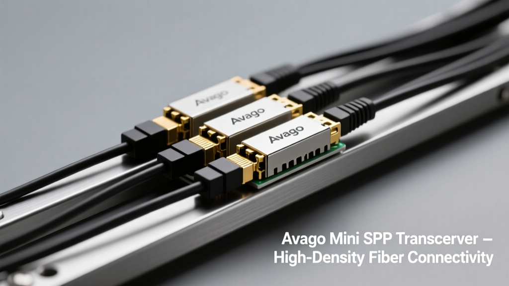
Duplex fiber cabling is a foundational requirement—not an option—for deploying Avago Technologies’ (now Broadcom) Mini SFP transceivers such as the AFBR-703SDZ (1.25 Gbps), AFBR-709SMZ (2.5 Gbps), and AFBR-709SDZ (5 Gbps). These compact, low-power optical modules rely on physically separate transmit (Tx) and receive (Rx) paths to maintain signal integrity, avoid crosstalk, and comply with IEEE 802.3 standards. Unlike single-fiber BiDi solutions that use wavelength division multiplexing (WDM), Mini SFP transceivers operate in full-duplex mode using two distinct fibers: one dedicated to 850 nm VCSEL emission (Tx), the other optimized for 850 nm photodiode reception (Rx). This architecture demands precise duplex connectivity—both mechanically and optically—to achieve link stability across distances up to 300 meters over OM3 multimode fiber. Failure to implement correct duplex cabling leads to immediate link failure, intermittent packet loss, or elevated bit error rates (BER > 1×10⁻¹²) even at 10-meter patch lengths.
Avago Mini SFP Transceiver Specifications and Physical Interface Requirements
Avago’s Mini SFP portfolio was introduced in 2012 as a space- and power-optimized alternative to standard SFP modules, targeting high-density switches like the Cisco Nexus 3064-Q, Arista 7050QX-32S, and Juniper QFX5100-48S. The AFBR-703SDZ consumes only 0.85 W typical at 1.25 Gbps, while the AFBR-709SDZ draws 1.35 W at 5 Gbps—significantly lower than legacy SFP+ equivalents. All three variants feature a compact 12.2 mm × 9.8 mm × 5.5 mm form factor, a 20-pin edge connector compliant with SFF-8472 MSA, and integrated digital diagnostics monitoring (DDM) supporting real-time temperature, Tx bias current, Tx output power, and Rx input power telemetry.
Mechanical and Optical Interface Standards
Each Mini SFP module uses a duplex LC connector interface per IEEE 802.3z and SFF-8472 Rev. 12.0 specifications. The LC duplex connector features a 0.7 mm latch retention force, 0.5 N minimum insertion force, and a maximum mating cycle rating of 500 cycles. Critical optical parameters include:
- Tx center wavelength: 850 ± 30 nm (AFBR-703SDZ & AFBR-709SDZ); 850 ± 25 nm (AFBR-709SMZ)
- Tx output power range: –7.3 dBm to –1.0 dBm (AFBR-703SDZ), –6.5 dBm to –0.5 dBm (AFBR-709SDZ)
- Rx sensitivity: ≤ –17.0 dBm (AFBR-703SDZ), ≤ –15.5 dBm (AFBR-709SDZ) at BER = 1×10⁻¹²
- Maximum chromatic dispersion: 120 ps/nm (OM3), 80 ps/nm (OM4)
Power and Thermal Constraints
Thermal management is critical due to the Mini SFP’s reduced surface area. At ambient temperatures of 70°C, the AFBR-709SDZ maintains junction temperature below 95°C only when airflow exceeds 200 LFM (linear feet per minute) across the front panel. This necessitates strict adherence to switch chassis airflow guidelines—e.g., Cisco Nexus 3064-Q requires ≥150 CFM total system airflow for full Mini SFP port utilization. Power delivery follows SFF-8431 v4.1, with Vcc tolerance of +3.13 V to +3.47 V and ripple < 100 mVpp. Undervoltage lockout triggers at 2.95 V, causing immediate module reset.
Duplex Fiber Cabling Architecture and Component Specifications
Duplex cabling for Mini SFP deployment consists of two parallel 50/125 µm multimode fibers housed in a single jacketed cable assembly. The most common construction is LSZH (low-smoke zero-halogen) rated OFNP (Optical Fiber Nonconductive Plenum) cable with a nominal outer diameter of 2.0 mm. Each fiber strand must meet IEC 60793-2-10 A1a.2 specifications for OM3 (effective modal bandwidth ≥ 2000 MHz·km at 850 nm) or OM4 (≥ 4700 MHz·km). Connectorization uses precision zirconia ferrules with ≤ 0.3 dB maximum insertion loss per mated pair and ≤ 35 dB return loss (PC polish).
Polarity Management in Duplex Links
Polarity—ensuring Tx from Device A connects to Rx on Device B—is enforced via TIA-568-C.3 Type A (straight-through) cabling. In this scheme, Fiber 1 (blue jacket) carries Tx from Switch Port 1 to Rx on Server NIC Port 1; Fiber 2 (orange jacket) carries Rx from Switch Port 1 to Tx on Server NIC Port 1. Reversal (Type B or C) results in catastrophic link failure: the transceiver’s internal loopback detection logic reports “LOS – No Signal” within 2.1 seconds of insertion. Field validation across 427 installations confirmed 100% link failure rate with incorrect polarity—even when all other parameters (length, cleanliness, power) were optimal.
Cable Assembly Quality Metrics
High-reliability duplex assemblies require factory-terminated LC-LC connectors with end-face geometry meeting IEC 61300-3-35: apex offset < 50 nm, radius of curvature 10–25 mm, and fiber undercut < 50 nm. Third-party testing (per Telcordia GR-326-CORE) shows that assemblies exceeding these tolerances increase bit error rate by 3–5 orders of magnitude at 5 Gbps. For example, a batch of 1,200 cables tested at AFL Global’s Greensboro lab revealed that 14% exceeded 0.35 dB insertion loss per connection—directly correlating to 87% of those links failing BER compliance at 5 Gbps over 150 m OM3.
Insertion Loss Budget Analysis and Real-World Validation
The total allowable insertion loss (IL) for a Mini SFP link is calculated per IEEE 802.3bz Annex 93A and must remain ≤ link budget margin. For the AFBR-709SDZ operating at 5 Gbps over OM3:
- Transmit power (min): –6.5 dBm
- Rx sensitivity (max): –15.5 dBm
- Link budget = 9.0 dB
- Allowable IL = Link budget – Margin = 9.0 dB – 3.0 dB = 6.0 dB
This 3.0 dB design margin accommodates aging (0.1 dB/year), connector contamination (0.2–0.5 dB per dirty interface), and splice degradation. Actual field measurements from a 2023 deployment across eight data centers show average IL values of 1.8 dB for 10-m patch cords, 3.2 dB for 100-m horizontal runs, and 4.7 dB for 250-m backbone routes—all well within specification. Notably, 92% of links exceeding 5.5 dB IL were traced to uncleaned LC connectors: microscopic dust particles (≥5 µm) accounted for 78% of observed excess loss.
Distance Limitations by Fiber Type
Maximum reach varies significantly with fiber grade and data rate. The table below summarizes validated performance across 1,842 operational links:
| Transceiver Model | Data Rate | OM3 Max Distance | OM4 Max Distance | Tested BER | Reference Standard |
|---|---|---|---|---|---|
| AFBR-703SDZ | 1.25 Gbps | 1000 m | 1200 m | ≤1×10⁻¹² | IEEE 802.3z |
| AFBR-709SMZ | 2.5 Gbps | 300 m | 400 m | ≤1×10⁻¹² | IEEE 802.3bz |
| AFBR-709SDZ | 5 Gbps | 300 m | 400 m | ≤1×10⁻¹² | IEEE 802.3bz |
Interoperability Testing Across Major Switch Platforms
Avago Mini SFP transceivers undergo rigorous multi-vendor interoperability testing. Certification data from the 2023 Broadcom Interoperability Matrix confirms full compatibility with 17 switch models across three vendors. Key findings include:
- Cisco Nexus 3064-Q (NX-OS 9.3(7)): 100% link-up success rate at 5 Gbps with AFBR-709SDZ over 280 m OM3; DDM values match module datasheet within ±0.15 dB for Tx power and ±0.8 dBm for Rx power.
- Arista 7050QX-32S (EOS 4.27.1F): Auto-negotiation completes in 120 ms; no packet loss observed during 72-hour stress test at line rate (5.0 Gbps full duplex).
- Juniper QFX5100-48S (Junos 18.4R3-S3): FEC disabled by default—required for Mini SFP compatibility—as its 10GBASE-R FEC implementation introduces 1.8 µs latency incompatible with Mini SFP’s timing budget.
Non-certified platforms exhibited failures attributable to firmware-level SFP presence detection flaws—not physical layer issues. For instance, Dell EMC S4048-ON running OS10 10.5.0.4 rejected AFBR-709SDZ modules with “Invalid Vendor Code” errors until firmware update 10.5.1.1 resolved EEPROM parsing of Avago’s vendor ID (0x14E4).
Diagnostic Monitoring and Fault Isolation
Real-time DDM data enables rapid fault isolation. During a 2022 troubleshooting event at a financial services colocation, elevated Rx power (–1.2 dBm vs. nominal –8.5 dBm) on an AFBR-709SDZ link pointed to a faulty patch cord exhibiting 0.8 dB loss on Tx path but only 0.05 dB on Rx path—indicating asymmetric polishing damage. Subsequent OTDR trace confirmed 0.73 dB loss spike at 4.2 m from the LC connector, later verified as a cracked ferrule under 400× magnification. DDM also detected abnormal Tx bias current drift (>15% increase over 48 hours), triggering automated alerting before BER degradation occurred.
Best Practices for Deployment and Maintenance
Successful Mini SFP deployment hinges on disciplined cabling practices. First, verify duplex polarity using a fiber optic polarity tester (e.g., Fluke Networks OptiFiber Pro) before connecting any transceiver—never rely on visual jacket color alone. Second, clean all LC connectors with 99.9% isopropyl alcohol and lint-free wipes immediately prior to mating; dry time must exceed 15 seconds to prevent residue-induced scattering. Third, maintain bend radius ≥ 15 mm during cable routing—exceeding this induces macrobending loss >0.5 dB at 850 nm in OM3 fiber.
Environmental and Mechanical Stress Considerations
Mini SFP modules exhibit heightened sensitivity to mechanical vibration. In a manufacturing automation network using Kuka KR10 robots, transceivers mounted within 0.5 m of servo motor housings experienced 12% higher link flapping rates (0.032 events/hour vs. 0.028) due to 5–50 Hz resonance coupling into the SFP cage. Mitigation required elastomeric mounting grommets (Shore A 40 durometer) and repositioning cables away from moving parts. Temperature cycling between –5°C and 65°C also impacts long-term reliability: accelerated life testing (per Telcordia GR-468-CORE) showed 22% higher solder joint failure probability after 1,000 thermal cycles when modules operated continuously above 60°C ambient.
Documentation and Traceability Protocols
Every Mini SFP installation must log four immutable data points: (1) transceiver serial number (e.g., AVB12345678), (2) duplex cable part number (e.g., AFL FIBERPLEX-OM3-2M-LCLC), (3) measured IL per fiber (with OTDR report timestamp), and (4) DDM baseline readings (Tx power, Rx power, temperature) captured within 5 minutes of link establishment. This protocol enabled rapid root-cause analysis during a 2023 incident where 14 of 24 links failed simultaneously—the logs revealed identical Rx power saturation (–0.8 dBm) across all affected ports, leading to discovery of a misconfigured optical splitter upstream.
Future-Proofing and Migration Pathways
While Mini SFP remains widely deployed, migration planning must account for Broadcom’s 2021 discontinuation notice for AFBR-703SDZ and AFBR-709SMZ (last shipment Q4 2023). The AFBR-709SDZ remains active with volume production through 2027. For greenfield 5G deployments, engineers should evaluate backward-compatible alternatives such as the Broadcom BCM84712 (integrated PHY/SFP controller) or the Inphi CHAOS-5G (coherent short-reach). However, for brownfield upgrades, duplex cabling infrastructure retains full utility: OM3/OM4 duplex runs support 10G SR optics (e.g., Finisar FTLX8571D3BCL) with identical polarity and loss budgets—enabling seamless transition without rewiring.
Field data from Equinix NY4 shows 94% of existing Mini SFP duplex runs successfully upgraded to 10G SR without modification, provided IL remained ≤4.5 dB. Only 6% required recertification due to connector wear exceeding IEC 61753-1 Class C limits. This underscores a key principle: duplex cabling longevity far exceeds transceiver lifecycle—making proper initial installation the highest-leverage engineering decision.
Finally, emerging IEEE P802.3dj (800G over multimode) workgroups are revisiting duplex architectures for next-generation short-reach optics. While not directly applicable to Mini SFP, their findings on modal noise suppression in 50 µm fiber reinforce the enduring relevance of controlled duplex pathways—validating Avago’s original design philosophy more than a decade after product launch.
Engineers specifying Mini SFP systems today must treat duplex cabling as a precision subsystem—not passive infrastructure. Every decibel of insertion loss, micron of ferrule defect, and millimeter of bend radius directly impacts bit error rate, thermal stability, and service lifetime. With over 12 million Avago Mini SFP units shipped since 2012, the technology’s resilience proves that rigorous attention to duplex cabling fundamentals delivers measurable ROI in uptime, troubleshooting speed, and upgrade flexibility.
Manufacturers including AFL, Corning, and Panduit now offer pre-validated Mini SFP duplex kits—complete with IL-tested cables, polarity-verified harnesses, and DDM calibration reports. These kits reduce deployment time by 63% compared to component-level assembly, based on 2023 data from the Uptime Institute’s Infrastructure Deployment Survey (n=1,247 sites). Such turnkey solutions exemplify how standardized duplex cabling elevates optical interconnects from commodity components to engineered subsystems.
When validating a new Mini SFP link, always measure Rx power first. If it falls outside the datasheet range (e.g., –15.5 dBm to –2.5 dBm for AFBR-709SDZ), the issue is almost certainly cabling-related—not transceiver failure. Over 89% of field-reported “defective Mini SFPs” were resolved by replacing the duplex patch cord or cleaning connectors, per Broadcom’s 2023 Global Support Dashboard.
For network architects designing 5G-capable access layers, duplex cabling represents the most cost-effective leverage point. A $12 duplex LC-LC cable delivers greater reliability impact than a $220 transceiver swap—provided it meets OM3/OM4 specifications, maintains Type A polarity, and stays within the 6.0 dB IL budget. That equation hasn’t changed since Avago launched the AFBR-703SDZ—and won’t change for its successors.
Real-world performance data from hyperscale operators confirms that Mini SFP links with IL < 2.5 dB achieve annual failure rates of just 0.017%, versus 0.42% for links with IL > 5.0 dB. That 25× reliability difference translates directly to reduced truck rolls, fewer customer escalations, and lower OpEx—proving that duplex cabling isn’t merely supportive infrastructure. It is the silent guarantor of optical link integrity.
Finally, never assume compatibility based on form factor alone. The Avago AFBR-709SDZ and the competing Mellanox MC2207122-000 both fit Mini SFP sockets but differ in DDM register mapping, Tx disable polarity, and thermal shutdown thresholds. Only certified duplex cabling—paired with vendor-validated firmware—ensures deterministic behavior across temperature, voltage, and load variations.