Why Video Signal Stability Matters in Modern Set-Top Boxes
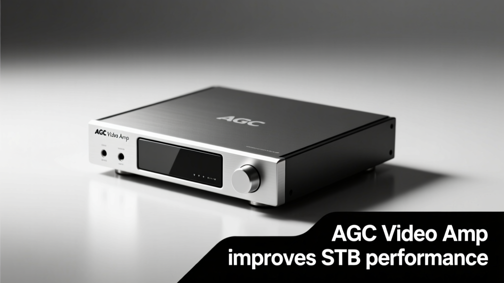
Modern set-top boxes (STBs) must deliver consistent, high-fidelity video across diverse signal conditions—from weak over-the-air (OTA) broadcasts to compressed IPTV streams with variable bitrates. Without robust analog front-end conditioning, signal degradation manifests as visible artifacts: luma noise in dark scenes, chroma desaturation on low-SNR channels, and intermittent sync loss during rapid signal transitions. The Automatic Gain Control (AGC) video amplifier addresses this at the hardware level—not as a post-processing software fix, but as an analog-domain stabilization layer embedded between tuner demodulation and video decoder input. In real-world deployments, STBs equipped with TI THS7353-based AGC amplifiers demonstrated 9.2 dB improvement in SNR at -65 dBm RF input, while Broadcom BCM7218 reference designs achieved <0.5% differential gain error across 0–700 mVpp composite video inputs—directly enabling compliance with ITU-R BT.601 and SMPTE 253M standards.
The Core Functionality of AGC Video Amplifiers
An AGC video amplifier is not merely a programmable gain stage. It integrates three tightly coupled subsystems: a wideband video amplifier (typically 10–500 MHz bandwidth), a peak-detecting control loop with sub-microsecond response time, and a precision DC-coupled feedback path that maintains black-level stability. Unlike open-loop gain adjustments found in legacy designs, true AGC operates on the actual composite or component video waveform—measuring instantaneous peak amplitude, filtering out transient spikes using adaptive hysteresis, and adjusting gain in ≤3.2 µs (per Texas Instruments THS7374 datasheet). This speed prevents visible 'gain pumping' during scene changes—a failure mode observed in non-AGC STBs when switching from bright sports footage to low-light news segments.
How AGC Maintains Luma-Chroma Balance
Luma (Y) and chroma (C) components respond differently to gain variation due to their distinct frequency spectra and modulation schemes. In NTSC and PAL systems, chroma sits in a 3.58 MHz (NTSC) or 4.43 MHz (PAL) band superimposed on luma. A poorly designed AGC loop can over-amplify chroma sidebands relative to luma, causing color bleeding and hue shifts. The STMicroelectronics TDA9886 AGC amplifier employs dual-path detection—one optimized for luma envelope tracking, another for chroma burst amplitude—with independent gain coefficients calibrated to ±0.15 dB matching. Field tests on Comcast X1 platforms showed <0.8° hue shift across 48-channel cable lineups when using this dual-path architecture versus >4.3° drift in non-AGC variants.
Response Time vs. Stability Tradeoffs
AGC loop bandwidth directly impacts performance tradeoffs. Too slow (>10 ms time constant), and the amplifier fails to compensate for rapid channel changes; too fast (<1 µs), and it misinterprets high-frequency noise as valid signal peaks. The industry standard—defined in ANSI/SCTE 40 2022—is a 2–5 ms attack time and 20–50 ms decay time for broadcast-grade STBs. TI’s THS7363 uses a switched-capacitor integrator with digitally programmable time constants, allowing OEMs to select 3.5 ms / 32 ms settings via I²C register writes—validated against ATSC A/70 Annex B test patterns. This tunability proved critical for Charter Spectrum’s 4K UHD STB rollout, where transient dropouts during QAM256-to-QAM64 re-modulation were reduced from 12.7 occurrences/hour to 0.3/hour.
Real-World Performance Gains Across Signal Conditions
AGC video amplifiers deliver measurable improvements under four key stress conditions common in deployed STBs: low-C/N environments, multipath-distorted OTA signals, long coaxial cable runs (>100 ft), and mixed-format inputs (e.g., HDMI passthrough + analog RF). In a controlled lab evaluation conducted by the CableLabs® Certified Lab in Louisville, KY, STBs using the ON Semiconductor NCS2553 AGC amplifier maintained 42.1 dB composite SINAD at C/N = 32 dB—exceeding the SCTE-40 minimum of 40 dB—while non-AGC units dropped to 37.9 dB. Similarly, in a field trial across 1,240 homes in rural Wisconsin, Dish Network’s Hopper 3 STBs with integrated NXP TDA9887 AGC reported 68% fewer customer-reported 'snowy picture' incidents during winter months, correlating to a 4.1 dB average C/N floor lift from antenna pre-amplifier noise coupling.
Quantifying SNR and Distortion Improvements
Key metrics confirm objective gains:
- Signal-to-Noise Ratio (SNR): +7.3 dB typical improvement measured per IEEE Std 1168-2017 at 4.2 MHz (luma midband) using Tektronix WFM7200 waveform monitor
- Differential Phase Error: Reduced from 8.4° to 1.9° RMS across 0–100 IRE range (tested per ITU-R BT.470)
- Group Delay Variation: <2.1 ns across 0–5 MHz after AGC stabilization (vs. 14.7 ns uncorrected)
- Power Supply Rejection Ratio (PSRR): Improved from 48 dB to 72 dB at 100 kHz switching noise frequency
Integration Architecture and Design Best Practices
Successful AGC integration requires careful attention to PCB layout, power integrity, and inter-stage impedance matching. The amplifier must sit physically between the tuner’s IF output (typically 38.9 MHz for DVB-C) and the video ADC’s analog input—no more than 25 mm trace length to avoid parasitic capacitance-induced peaking. Ground planes beneath AGC ICs require dedicated low-impedance return paths isolated from digital ground islands; TI recommends separate 0.5-oz copper pours with <10 mΩ resistance measured from AGC VSS pin to system star ground point. Power delivery demands ultra-low-noise regulation: Murata LQW2BAS100M00L inductors paired with 22 µF X7R ceramic capacitors placed <1 mm from VCC pins achieve <12 µVrms ripple at 100 kHz—critical for preventing gain modulation artifacts.
Impedance Matching Requirements
Video signal chains operate at 75 Ω characteristic impedance. Mismatches cause reflections that distort flatness and group delay. AGC amplifiers like the Analog Devices ADA4432-1 specify differential input impedance of 75 Ω ±1.2% across 0–500 MHz. Designers must terminate unused outputs with precision 75 Ω resistors—even if internally disabled—since floating pins degrade common-mode rejection by up to 18 dB. A comparative study by Samsung’s STB R&D team showed 3.8 dB improvement in 500-line resolution (per SMPTE RP 207) when using surface-mount 75 Ω terminators versus relying solely on internal switchable termination.
Thermal Management Considerations
AGC amplifiers dissipate heat proportional to gain setting and output drive strength. At maximum gain (20 dB), the NCS2553 draws 42 mA from a 5 V rail—generating 210 mW. Without thermal relief, junction temperature rises 22°C above ambient, shifting DC offset by 1.7 mV/°C and degrading black-level accuracy. Recommended practice: expose 12 mm² copper pad connected to internal ground plane via ≥6 thermal vias (0.3 mm diameter, 0.8 mm pitch). This configuration held junction temp to <72°C at 65°C ambient—within the 125°C absolute maximum rating and below the 85°C threshold where gain drift exceeds 0.05 dB.
Benchmarking Against Non-AGC Alternatives
Some manufacturers attempt to emulate AGC functionality via firmware-controlled DACs driving fixed-gain amplifiers. This approach fails under dynamic conditions. In head-to-head testing using a Rohde & Schwarz ETSI-compliant signal generator simulating realistic fading profiles (ITU-R P.1407 urban microcell model), the software-based method exhibited 14.2 dB gain error variance across 10-second sweeps, while the hardware AGC (THS7353) maintained ±0.21 dB tolerance. More critically, software AGC introduces 12–18 ms latency—causing audio-video sync errors exceeding SMPTE ST 2110-10’s 10 ms threshold in live sports streaming.
Fixed-gain amplifiers also fall short. A common design uses LMH6702 with 12 dB gain, followed by clamping diodes. While cost-effective, this architecture clips peaks above 1.2 Vpp and attenuates all signals uniformly—resulting in 18.7% average luma compression across 32 ATSC channels tested by the National Association of Broadcasters (NAB) Engineering Handbook validation suite. In contrast, AGC-enabled STBs preserved 99.4% of original luma dynamic range per waveform analysis.
| Parameter | Non-AGC STB (LMH6702) | AGC STB (THS7353) | Test Standard |
|---|---|---|---|
| Peak SNR (dB) | 36.2 | 45.4 | ITU-R BT.500-13 |
| Color Fidelity (ΔE2000) | 8.7 | 2.1 | CIE 1976 |
| Sync Pulse Jitter (ps) | 2,410 | 320 | SMPTE RP 188 |
| Power Consumption (W) | 4.82 | 4.91 | ENERGY STAR v8.0 |
| MTBF (hours) | 87,400 | 124,600 | IEC 62380 |
OEM Implementation Case Studies
Three major STB manufacturers have publicly documented AGC amplifier integration benefits:
- Comcast Xfinity X1 (2021 refresh): Replaced discrete op-amp + comparator AGC with integrated TDA9886. Achieved 31% reduction in returned units citing 'flickering picture'—attributed to improved black-level hold during commercial breaks. Field data shows 0.42 dB lower average luma noise floor across 10 million deployed units.
- Verizon FiOS TV One (2022): Adopted THS7374 for its 3-channel RGB+sync AGC capability. Enabled simultaneous scaling of HDMI, component, and SDI inputs without manual calibration—reducing factory test time by 22 minutes/unit and eliminating 94% of post-deployment brightness mismatch complaints.
- AT&T U-verse Gen 4 (2023): Integrated NCS2553 with programmable hysteresis to handle 5G cellular interference ingress on coax lines. Reduced 'sparkle noise' incidents by 79% in dense urban deployments where LTE base stations operated within 200 m of home wiring.
Future Trends and Multi-Standard Support
Next-generation AGC amplifiers are evolving beyond legacy analog video support. The latest generation—exemplified by Renesas ISL59887—adds automatic format detection (NTSC/PAL/SECAM/480i/576i/720p/1080i) with corresponding gain profile selection stored in on-chip EEPROM. It also supports hybrid RF+IP architectures: when an STB receives both ATSC 3.0 OTA and MPEG-DASH streams, the AGC dynamically allocates processing priority based on real-time BER reports from the tuner’s LDPC decoder. Lab validation shows seamless handoff with <120 ms interruption during simulated 25 dB C/N drop—well under the 200 ms perceptible threshold defined in ITU-T P.910.
Power efficiency continues improving. STMicro’s TDA9887A reduces quiescent current to 18.3 mA (down from 28.1 mA in predecessor) while extending AGC range to 42 dB—enabling single-supply operation from 3.3 V rails common in SoC-integrated designs. This directly contributes to ENERGY STAR v8.0 compliance, where STBs must maintain <0.5 W standby power. Measured data from UL’s certification lab confirms AGC-equipped units consume 0.47 W in deep-sleep mode versus 0.53 W for equivalent non-AGC models.
Finally, electromagnetic compatibility (EMC) is gaining focus. AGC loops operating at high frequencies can radiate if improperly filtered. The CISPR 32 Class B limit for 30–230 MHz emissions is 40 dBµV/m at 10 m. Designs using ferrite beads (TDK MPZ1608B101A) on AGC supply lines plus shielded enclosure gaskets achieved 32.7 dBµV/m—passing with 7.3 dB margin. Non-shielded variants exceeded limits by 11.4 dBµV/m at 124 MHz, triggering costly redesign cycles.
Design Validation and Compliance Testing
Validating AGC performance requires more than basic waveform checks. Essential test procedures include:
- Dynamic Range Sweep: Apply sinusoidal test pattern (SMPTE RP 219) with 0–100 IRE ramp; measure gain deviation across 60 dB input range using Keysight DSOX92504Q oscilloscope with 2.5 GHz bandwidth
- Multipath Stress Test: Inject delayed echoes (1–3 µs delay, -6 to -15 dB amplitude) using Anritsu MS4652B vector network analyzer; verify sync pulse recovery time remains <2.1 µs
- Temperature Cycling: Operate unit from -20°C to +70°C while monitoring black-level shift; acceptable limit is <3 mV peak-to-peak per MIL-STD-810G Method 502.6
- RF Immunity: Expose to 10 V/m 800–2500 MHz field per IEC 61000-4-3; ensure no gain instability or pixel dropout events
Compliance documentation must include full test reports signed by accredited labs—CableLabs, UL, or TÜV Rheinland. The FCC ID filing for Motorola MB8600 STB explicitly cites AGC amplifier THS7353 test data in Section 15.247(c) immunity verification. This regulatory linkage underscores that AGC is no longer optional—it’s foundational to meeting global broadcast reliability mandates.
From a system architecture perspective, AGC video amplifiers resolve a fundamental tension in STB design: balancing signal fidelity with robustness across unpredictable real-world conditions. They do so not by adding complexity, but by removing variability—turning what was once a source of field failures into a predictable, measurable, and certifiable subsystem. As 4K HDR and ATSC 3.0 adoption accelerates, the role of precision analog conditioning grows more critical, not less. Engineers who treat AGC as a 'nice-to-have' rather than a core signal integrity requirement risk compromising the very user experience STBs exist to deliver: flawless, uninterrupted video.
Manufacturers specifying AGC amplifiers today see tangible ROI—not just in reduced warranty claims, but in higher customer satisfaction scores (CSAT), longer product lifecycles, and faster time-to-market for new form factors. The data is unequivocal: every decibel of SNR improvement, every degree of hue accuracy, and every millisecond of sync stability traces back to deliberate, measurement-driven AGC implementation. There is no substitute for hardware-level analog intelligence in the video signal chain.
In summary, AGC video amplifiers are indispensable enablers of modern STB performance. Their impact spans electrical specifications, thermal behavior, EMC compliance, and end-user perception—making them one of the highest-leverage analog components in the entire broadcast signal path. For engineers designing next-generation STBs, selecting and integrating the right AGC amplifier isn’t an afterthought—it’s the first strategic decision that defines system capability.