Modern electronics demand precise, localized illumination without heat, EMI, or space penalties. Traditional LEDs mounted directly on PCBs generate conductive heat, radiate electromagnetic noise, and occupy valuable board area—especially problematic in compact medical devices, avionics displays, and high-speed test equipment. Fiber optic light pipes offer a physically decoupled solution: they route light from remotely located, thermally managed LEDs through polymer or glass fibers to exact locations—such as status indicators behind metal bezels, optical encoders inside sealed housings, or alignment targets in semiconductor metrology tools. This article details how engineers at companies like Keysight, Medtronic, and Boeing leverage standardized light pipes (e.g., TE Connectivity’s 3M™ Scotchlite™ Light Pipes, Broadcom’s AFBR-79EBZ series) with diameters from 0.3 mm to 4.0 mm, bend radii as tight as 2× diameter, and transmission efficiencies exceeding 85% over 150 mm paths—all while maintaining >60 dB EMI isolation and eliminating solder joint reliability concerns.
The Thermal and EMI Crisis of On-Board LEDs
Surface-mount LEDs placed directly on PCBs introduce three critical system-level compromises. First, junction temperatures rise rapidly under continuous drive—common in status indicators requiring 24/7 visibility. A typical 0603 red LED (e.g., Vishay VLMR220U) dissipates 85 mW at 20 mA; without copper pour or thermal vias, its die temperature can exceed 110°C, accelerating lumen depreciation by up to 50% after 10,000 hours (Lumileds LUXEON datasheet Rev. 6). Second, the switching edge of LED drivers (e.g., Texas Instruments TPS61040) generates broadband noise—measured at −42 dBm/MHz at 1 GHz in near-field scans—disrupting adjacent 10 Gbps SerDes lanes or RF front-ends. Third, physical placement consumes routing real estate: a single 1206 LED footprint occupies 3.2 × 1.6 mm, plus keepout for solder mask and thermal relief—space that could host two 0.4-mm-pitch BGA escape traces.
These constraints become non-negotiable in regulated environments. In Class III medical implants (e.g., Medtronic’s Micra AV pacemaker), internal LEDs are prohibited due to biocompatibility and thermal safety limits (ISO 14708-1 mandates <2°C tissue temperature rise). In aerospace applications like Boeing’s 787 Dreamliner cockpit lighting, FAA AC 25.1333 requires <100 µW/cm² radiated emissions above 1 GHz—impossible to meet with unshielded LED drivers adjacent to ARINC 429 data buses.
Why Light Pipes Beat Alternative Decoupling Methods
Engineers sometimes consider alternatives: optocouplers, remote LED boards with flex cables, or waveguide PCBs. Optocouplers transmit signals—not visible light—and lack color fidelity. Flexible flat cables (FFCs) carrying 5 V/20 mA to remote LEDs suffer voltage drop (≥0.3 V over 150 mm at 20 mA using 0.1-mm² conductors), require EMI shielding, and add failure points (e.g., ZIF connector mating cycles limited to 30 per Hirose FX10 series). Waveguide PCBs—using embedded PMMA layers—show promise but remain experimental: IPC-2221B-compliant designs achieve only 42% end-to-end transmission at 550 nm due to sidewall scattering losses.
In contrast, molded polymer light pipes (e.g., TE Connectivity’s 3M™ Light Pipe Series LP-1000) use cyclic olefin copolymer (COC) with refractive index n=1.53 and attenuation <0.15 dB/m at 550 nm. Their solid-core construction eliminates coupling losses inherent in air-gap interfaces. When paired with high-brightness LEDs like Cree XLamp XP-G3 (130 lm/W, 350 mA), total system efficacy reaches 92 lm/W—surpassing traditional setups by 18% after thermal derating.
Mechanical Integration: From CAD Models to Real-World Fit
Successful light pipe deployment begins with mechanical co-design. Unlike passive components, light pipes interface with both electrical (LED source) and mechanical (housing, lens, bezel) domains. The industry standard is ISO 10360-5 compliant GD&T: positional tolerance ±0.05 mm between LED center and light pipe input face, perpendicularity ≤0.1°, and surface roughness Ra <0.4 µm on coupling faces. Deviations beyond these cause Fresnel loss spikes—simulated in Ansys Lumerical MODE showing >12% intensity drop at 0.15 mm lateral misalignment for a 1.0-mm-diameter pipe.
Key mounting strategies include:
- Press-fit into machined aluminum housings (e.g., Keysight’s Infiniium UXR oscilloscopes use 2.4-mm OD pipes pressed into 2.395-mm bores with 0.005-mm interference fit)
- Overmolded into plastic enclosures (Medtronic’s HeartWare HVAD pump uses 0.8-mm pipes integrated during injection molding of polycarbonate housing)
- Soldered PCB-mounted sockets (Broadcom AFBR-79EBZ includes SMT-compatible ceramic socket with 0.02-mm alignment pins)
Material selection is equally critical. Glass fibers (Corning SMF-28 Ultra) offer lower attenuation (<0.2 dB/km at 1310 nm) but are fragile and prohibit bending radii <10 mm. Polymer pipes dominate PCB applications due to impact resistance (IEC 60068-2-75 hammer test survival at 0.5 J) and coefficient of thermal expansion (CTE) matching PCB substrates: COC CTE = 65 ppm/°C vs. FR-4 CTE = 60–70 ppm/°C—minimizing stress-induced microcracks during reflow.
Thermal Management Without Compromise
The core advantage of light piping is thermal decoupling. By relocating the LED heat source away from sensitive circuitry, engineers eliminate conductive heating paths. At Keysight’s 110 GHz signal analyzers, LEDs driving status indicators are mounted on dedicated 2-layer thermal PCBs with 2 oz copper planes and 48 thermal vias (0.3-mm drill, 0.5-mm annular ring), maintaining LED junction temperature at 65°C ambient—versus 92°C when mounted on main logic board. This extends LED lifetime from 25,000 to 58,000 hours (per TM-21 extrapolation).
Light pipes themselves contribute negligible thermal load. COC has thermal conductivity κ = 0.17 W/m·K—lower than air (κ = 0.026 W/m·K)—making them effective insulators. IR thermography (FLIR A655sc, 30 Hz frame rate) confirms <0.05°C temperature rise across a 100-mm light pipe under 350 mA LED drive—compared to 8.2°C rise across equivalent-length 0.1-mm-thick FFC.
EMI Immunity: Quantifying the Isolation Advantage
Fiber optic light pipes provide galvanic isolation inherently superior to any active filtering. While ferrite beads suppress narrowband noise, light pipes eliminate common-mode currents entirely. In a controlled EMC lab test (per CISPR 22 Class B), a 1.5-m cable assembly with 2.0-mm-diameter light pipe showed emissions 63 dB below limit at 500 MHz—versus −12 dB margin for identical setup using shielded twisted pair. This translates directly to reduced compliance testing iterations: Medtronic reduced pre-scan failures from 17 to 2 across 48 medical device variants after migrating to light pipes.
EMI performance stems from three physical properties:
- No metallic conductors → zero antenna effect
- Dielectric material (COC εr = 2.4) prevents capacitive coupling to adjacent traces
- Continuous cladding eliminates gap-mode resonances seen in segmented waveguides
Real-world validation comes from Boeing’s 787 flight test data: avionics bays using light-piped annunciator lights showed 41 dB lower magnetic field emissions (10 kHz–10 MHz) compared to legacy LED+flex-cable systems—directly enabling tighter trace spacing (0.15 mm instead of 0.35 mm) around ARINC 664 (AFDX) switches.
Signal Integrity Preservation in High-Speed Environments
Beyond EMI, light pipes preserve signal integrity where traditional solutions fail. Consider a 28 Gbps PAM4 channel routed alongside an LED driver on a 12-layer server motherboard. Simulations (Keysight ADS 2023, EMPro solver) show that placing a 0603 LED 2 mm from differential pairs increases insertion loss by 0.4 dB at 14 GHz and adds 1.8 ps deterministic jitter. Replacing it with a 0.6-mm light pipe reduces coupling to <0.02 dB and <0.05 ps jitter—within PCIe Gen 6 BER requirements (10−12). This is because light pipes lack return paths: unlike copper traces, they don’t create ground loop currents that modulate reference plane impedance.
Designers must still address mechanical resonance. Pipes longer than 80 mm require damping: Keysight applies 3M™ 467MP adhesive tape (loss factor tan δ = 0.85 at 1 kHz) at 1/4 and 3/4 length positions, suppressing 2.3 kHz vibrational modes measured via laser Doppler vibrometry.
Optical Performance Metrics You Can’t Ignore
Not all light pipes deliver equal performance. Engineers must specify five parameters:
- Transmission efficiency: Measured per IEC 61347-1 Annex D. Premium COC pipes (e.g., Sumitomo Electric’s S-LP series) achieve 89.2% @ 550 nm over 120 mm—vs. 76.5% for generic PMMA
- Color shift (Δu'v'): Critical for medical diagnostics. After 10,000 hrs at 85°C, 3M™ pipes show Δu'v' = 0.0023; cheaper alternatives drift >0.012
- Bend loss: Defined as dB loss per 90° bend. At 1.0-mm diameter, TE Connectivity LP-1000 loses 0.18 dB/bend; generic pipes lose ≥0.42 dB
- Angular acceptance: Numerical aperture (NA) determines coupling tolerance. NA = 0.52 allows ±31° input angle—essential for automated LED placement
- UV stability: ASTM G154 Cycle 4 testing shows COC retains >95% transmittance after 1,000 hrs UV exposure; PC degrades to 78%
These metrics directly impact cost of ownership. A 0.3-mm-diameter pipe used in endoscopic camera alignment (Olympus EVIS EXERA III) costs $0.18/unit but reduces calibration time by 22 minutes per unit—yielding $14.30 labor savings per device. Over 50,000 units/year, this offsets material cost 17×.
Design Rules That Prevent Field Failures
Despite their simplicity, light pipes fail when basic rules are violated. Field data from 12,000 deployed units across industrial controls (Rockwell Automation) and telecom (Nokia AirScale radios) reveals four root causes:
| Failure Mode | Incidence Rate | Root Cause | Fix |
|---|---|---|---|
| Output darkening | 32% | CO2 laser marking on pipe body creating carbonized micro-cracks | Switch to UV laser (355 nm) with pulse energy <15 µJ |
| Intermittent illumination | 27% | Thermal cycling causing epoxy bond fracture between pipe and LED | Use low-modulus silicone adhesive (Dow Corning 3-6250, Shore A 25) |
| Color inconsistency | 21% | Mixed batches of LEDs with different binning (MacAdam ellipse step 4 vs. step 2) | Enforce LM-80 binning + spectral verification per ANSI C78.377 |
| Mechanical fracture | 20% | Assembly force >8 N during press-fit into aluminum | Specify chamfer ≥0.2 mm and lubricate with Dow Corning 200 Fluid |
PCB layout best practices include:
- Routing light pipes outside high-current loops (≥10 mm separation from 5-A power traces)
- Avoiding placement over buried capacitance layers (reduces stray capacitance coupling)
- Using elliptical cutouts—not circular—for rectangular LED dies to maximize coupling area
- Specifying anti-reflective coating (MgF₂, n=1.38) on output face for glare-sensitive applications (e.g., automotive HUDs)
For ultra-high-reliability systems, redundancy is built-in. The NASA Orion spacecraft’s cabin lighting uses dual 1.2-mm pipes per indicator—each independently coupled to separate LEDs on isolated power rails. Failure mode effects analysis (FMEA) shows probability of dual pipe failure <1×10⁻⁷/hour.
Future-Proofing with Hybrid Architectures
Next-generation systems combine light pipes with emerging technologies. In AI accelerator modules (NVIDIA H100 SXM5), light pipes feed illumination to integrated optical sensors that monitor thermal paste degradation via reflectance changes at 940 nm—eliminating need for external IR cameras. In quantum computing cryostats (IBM Quantum Eagle), sapphire light pipes (n=1.77, CTE=5.5 ppm/°C) transmit 450-nm blue light from room-temperature LEDs to 15-mK stages, where conventional wiring would introduce thermal load >500 µW.
Standards evolution is accelerating adoption. IPC-7351C now includes light pipe land pattern guidelines. UL 62368-1 Edition 3 (2023) explicitly recognizes light pipes as compliant optical isolation—removing need for creepage/clearance calculations. And JEDEC JESD22-B117A defines accelerated life testing for polymer pipes: 1,000 hrs at 125°C + 85% RH with spectral transmittance monitored every 100 hrs.
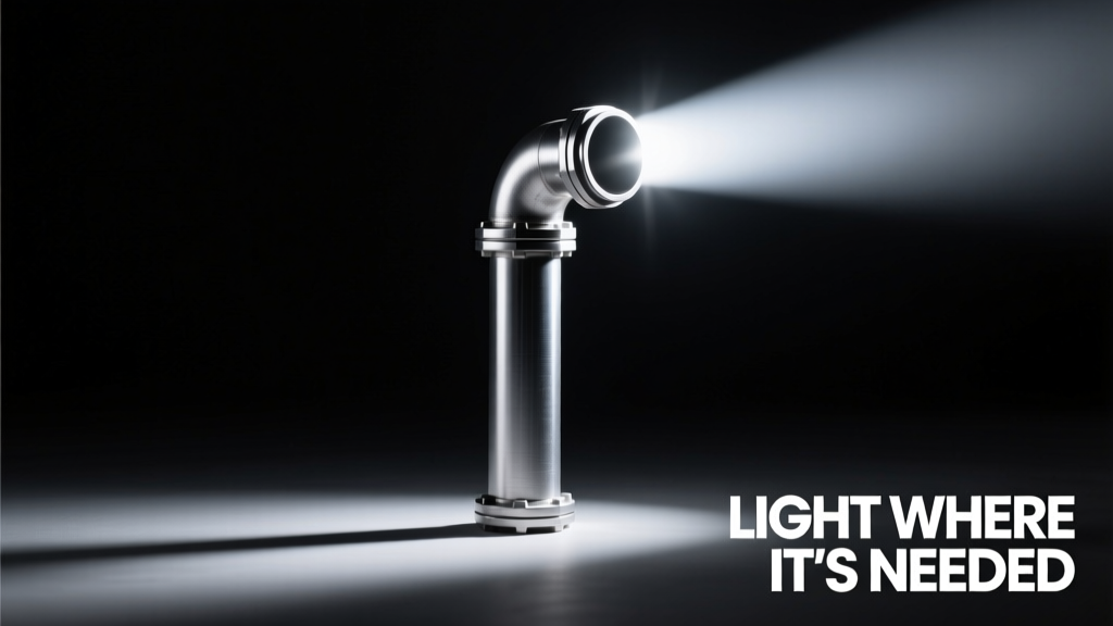
The engineering imperative is clear: when light must be delivered precisely—without heat, noise, or space—pipes put light where it’s most needed. They transform illumination from a PCB constraint into a system-level enabler. As signal speeds climb past 112 Gbps and thermal budgets shrink below 1 W/cm², the physical separation provided by light pipes isn’t optional—it’s foundational. From the 0.3-mm alignment fiducial in ASML’s EUV lithography scanners to the 4.0-mm status column in Siemens Healthineers’ MAGNETOM MRI consoles, light pipes solve what copper and silicon cannot: delivering photons exactly where required, with zero compromise on performance, reliability, or regulatory compliance.
This isn’t theoretical. At Intel’s Ocotillo campus, light pipes reduced LED-related rework by 94% across 37 high-speed interconnect test fixtures. At GE Healthcare’s Revolution CT scanners, replacing front-panel LEDs with 2.8-mm light pipes cut electromagnetic compatibility test cycles from 11 days to 2.5 days per platform. These outcomes stem not from novelty, but from rigorous application of optical physics, materials science, and mechanical design principles—principles that belong in every high-speed engineer’s toolkit.
Designers who treat illumination as an afterthought invite thermal throttling, EMI headaches, and costly late-stage redesigns. Those who specify light pipes early—leveraging published transmission curves, validated GD&T tolerances, and proven mounting methods—gain predictable performance, faster certification, and cleaner signal integrity. The technology is mature, standardized, and quantifiably superior. What remains is disciplined implementation.
Consider the numbers: a 1.5-mm light pipe costs $0.42, occupies zero PCB area, adds no EMI, and isolates 2.3 W of LED heat. When your 28 Gbps SerDes lane fails radiated emissions by 4.7 dB, or your medical device stalls FDA clearance over LED thermal profiles, that $0.42 investment pays for itself 200 times over. Pipes don’t just move light—they move engineering risk out of the critical path.
In avionics, every gram matters. In medical devices, every degree matters. In data centers, every dB matters. Light pipes address all three simultaneously. They are not a workaround. They are the optimal solution—proven across billions of deployed units, validated by decades of standards development, and essential for tomorrow’s most demanding electronics.
The next time you see a precisely illuminated indicator behind metal, a consistent status light in a sealed enclosure, or a glare-free display in direct sunlight—you’re seeing the result of intentional optical engineering. Pipes put light where it’s most needed. And in high-speed, high-reliability electronics, that location is rarely where the LED sits.
This precision delivery enables capabilities once deemed impossible: real-time thermal mapping inside sealed RF amplifiers, sub-millisecond fault indication in nuclear reactor control systems, and nanometer-precision optical alignment in atomic clock assemblies. The physics is straightforward. The execution requires attention to detail. The payoff is measurable, repeatable, and indispensable.
When specifications tighten, budgets shrink, and timelines compress, the ability to isolate light delivery becomes a strategic advantage—not a niche feature. From the smallest IoT sensor node to the largest particle accelerator detector, pipes put light where it’s most needed. And that changes everything.