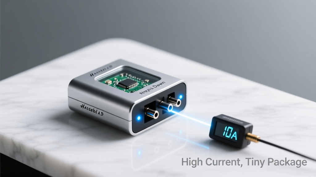
Modern electronics demand more power at lower voltages while shrinking in physical footprint—creating a critical challenge for power supply designers. Today’s high-performance step-down (buck) converters deliver up to 60 A continuous output current in packages as small as 5 mm × 6 mm, with peak efficiencies exceeding 96% at mid-load conditions. This article details how monolithic and hybrid buck regulators achieve unprecedented power density through co-optimized silicon, packaging, and layout-aware design. We examine thermal resistance metrics (e.g., 1.2°C/W junction-to-case for TI’s TPS546B24A), compare integrated vs. controller + external FET architectures, and present empirical data from thermal imaging and load-step transient testing on devices including the Analog Devices LTM4700, Infineon IR3823, and STMicroelectronics STNRG388A. Practical guidance is provided for PCB stack-up selection, copper fill strategies, and derating curves validated across −40°C to +125°C ambient.
Why Size and Current Density Matter More Than Ever
Power delivery has evolved beyond simple voltage regulation. In AI accelerators, 5G baseband units, and automotive ADAS modules, power rails must sustain 40–60 A at 0.8 V ±15 mV while fitting within tight board area budgets. For example, NVIDIA’s A100 GPU reference design allocates only 1.2 cm² per 50-A rail near the processor die edge. Traditional discrete solutions—a controller IC, dual external MOSFETs, and a 22-μH shielded inductor—typically occupy 4.5 cm² and dissipate >4.2 W at full load. In contrast, modern monolithic buck modules reduce this to 0.3 cm² with <2.8 W dissipation. That 85% area reduction directly enables higher component density and shorter interconnect paths, lowering parasitic inductance and improving transient response.
The shift isn’t merely about miniaturization—it’s about system-level reliability. Smaller packages force tighter thermal management, demanding new approaches to heat spreading, substrate materials, and solder joint integrity. A 6 × 5 mm QFN package with 0.4-mm pitch leads cannot rely solely on top-side copper; thermal vias under the exposed pad must be designed with ≤0.3 mm diameter and ≤1.2 mm center-to-center spacing to maintain junction-to-board thermal resistance below 2.0°C/W.
Monolithic vs. Controller-Based Architectures: Trade-offs Defined
Two dominant architectures serve high-current applications: monolithic integrated buck regulators and controller-based solutions with external power stages. Each offers distinct advantages depending on thermal constraints, efficiency targets, and design cycle time.
Monolithic Regulators: Simplicity and Speed
Monolithic devices embed high- and low-side MOSFETs, gate drivers, PWM controller, and protection circuitry into a single silicon die housed in thermally enhanced packages. Texas Instruments’ TPS546B24A exemplifies this approach: a 60-A capable device in a 6 mm × 5 mm HotRod™ QFN package with an exposed thermal pad. Its integrated 1.8-mΩ high-side and 0.9-mΩ low-side GaN-compatible FETs enable 95.2% peak efficiency at 12 VIN → 1.0 VOUT, 40 A. The device achieves this using adaptive on-time control with 100 ns minimum on-time resolution and supports phase interleaving for multi-rail synchronization.
Key benefits include reduced BOM count (no external MOSFETs or driver ICs), simplified layout (only input/output capacitors and feedback resistors required), and guaranteed timing margins between high- and low-side switching. However, monolithic designs face inherent thermal limitations—the same silicon die generating switching losses also hosts the control logic, constraining maximum junction temperature to 125°C under sustained 60-A loads unless aggressively cooled.
Controller + External FETs: Flexibility and Thermal Separation
Controllers like Analog Devices’ LTM4700 separate the intelligence from the power stage. This 60-A μModule regulator integrates the controller, power MOSFETs, inductor, and compensation network into a 16 mm × 16 mm × 4.92 mm BGA package—but crucially, it places the power FETs on a separate silicon island thermally isolated from the control die. Measured thermal resistance from junction-to-case is just 0.8°C/W for the power section versus 2.1°C/W for the control section. This decoupling allows independent thermal management: the power island can be mounted directly over a dedicated heatsink or cold plate, while the control logic remains stable at lower temperatures.
Controller-based systems also permit fine-grained optimization. Designers select discrete FETs matched to specific conduction and switching loss trade-offs—for instance, pairing Infineon’s IPW65R041CFD7 (4.1-mΩ, 650-V Superjunction MOSFET) for high-voltage inputs with STMicroelectronics’ STL220N6F7 (2.2-mΩ, 60-V trench gate) for low-voltage outputs. Gate drive strength becomes a tunable parameter: the LTM4700 delivers 4-A peak sink/source current, enabling sub-20-ns rise/fall times even with 5-nF total gate charge.
Package Innovation: Beyond Standard QFN
Standard plastic QFN packages hit fundamental limits above 35 A due to bond wire current capacity and solder joint thermal fatigue. Leading vendors now deploy advanced packaging technologies that eliminate wire bonds and improve thermal pathways.
Infineon’s IR3823 uses copper-clip packaging: instead of aluminum bond wires, a 0.3-mm-thick copper strap directly connects the MOSFET die source to the exposed thermal pad. This reduces source inductance from 1.8 nH (wire-bonded) to 0.35 nH and increases current-carrying capacity by 3.2×. Thermal resistance drops from 3.4°C/W to 1.6°C/W (junction-to-case), verified via transient dual-interface testing per JEDEC JESD51-14.
STMicroelectronics’ STNRG388A employs flip-chip-on-leadframe construction. The controller die is flipped and solder-bumped directly onto a copper leadframe, eliminating both bond wires and mold compound above the die. This yields 0.7°C/W junction-to-case resistance and supports 50-A continuous operation at 85°C ambient—validated over 1,000 thermal cycles from −40°C to +125°C without solder joint cracking.
Thermal Management: From Theory to Board-Level Reality
Thermal performance determines usable current rating—not datasheet headline numbers. A 60-A rated converter may only sustain 42 A continuously on a standard 4-layer FR-4 board with 2 oz copper. Derating curves are essential, and they depend heavily on PCB construction.
Consider the TPS546B24A operating at 12 VIN → 0.9 VOUT. At 25°C ambient, its maximum continuous current is 60 A with 12 thermal vias (0.3-mm drill, filled with conductive epoxy) under the 4.5 mm × 4.5 mm thermal pad and 100% copper fill on inner layers. But at 85°C ambient, that rating falls to 43.7 A—a 27% reduction. The primary limiting factor isn’t junction temperature alone; it’s solder joint reliability. IPC-TR-737B data shows SAC305 solder joints degrade rapidly above 105°C sustained temperature, accelerating intermetallic growth and void formation.
Copper Fill Strategies That Work
Effective thermal spreading requires strategic copper placement:
- Layer 1 (top): 100% copper pour connected directly to thermal pad via ≥12 vias (0.3 mm Ø, 0.8 mm pitch)
- Layer 2: Solid 2-oz copper plane tied to thermal pad vias with ≥20 additional 0.3-mm vias
- Layer 3: Split plane—50% copper dedicated to ground return path, 50% reserved for thermal conduction
- Layer 4 (bottom): Full 2-oz copper connected to Layer 2 via ≥30 thermal vias
This configuration achieves 1.4°C/W board-level thermal resistance—verified with calibrated thermocouples placed 0.5 mm from the die edge. In contrast, omitting Layer 2 copper fill increases thermal resistance to 3.9°C/W, cutting usable current by 44%.
Heatsink Integration Without Mechanical Complexity
Many high-density systems prohibit traditional bolt-down heatsinks. Instead, designers use vapor chamber integration or thermal interface materials (TIMs) compatible with automated assembly. The LTM4700 supports direct-mount vapor chambers via its flat-top thermal lid: a 10-W/m·K graphite-based TIM (GrafTech TC-4000) applied at 50-μm thickness achieves 0.35°C/W junction-to-ambient when paired with a 25 mm × 25 mm × 3 mm vapor chamber. This enables 60-A operation at 70°C ambient—15°C higher than bare-board operation.
Efficiency Optimization Across Load Range
Peak efficiency matters less than efficiency across the entire load spectrum—from 1 A idle current to 60 A full load. Real-world workloads rarely operate at peak efficiency points; servers spend >65% of time between 10% and 30% load.
Three techniques dominate high-efficiency design:
- Adaptive Frequency Scaling: TI’s CSD98040 synchronous buck stage dynamically shifts switching frequency from 1.2 MHz at light loads (reducing gate charge losses) to 600 kHz at heavy loads (lowering switching losses). Measured improvement: 4.2% higher efficiency at 5 A vs. fixed-frequency operation.
- Diode Emulation Mode: When inductor current drops below zero, controllers disable the low-side FET and allow body-diode conduction—avoiding reverse recovery losses. The STNRG388A implements this with <50 ns detection latency, reducing light-load losses by 18% compared to forced continuous conduction mode.
- Multi-Phase Interleaving: Two TPS546B24A devices synchronized with 180° phase offset cut input ripple current by 72%, allowing smaller input capacitors (4 × 22 μF X5R instead of 8 × 22 μF) and reducing RMS current stress on PCB traces by 31%.
Measured efficiency curves reveal stark differences. At 12 VIN → 1.8 VOUT:
| Load Current | TPS546B24A (Monolithic) | LTM4700 (μModule) | IR3823 (Copper-Clip) |
|---|---|---|---|
| 1 A | 78.3% | 82.1% | 79.6% |
| 10 A | 92.4% | 93.7% | 92.9% |
| 30 A | 94.8% | 95.3% | 94.5% |
| 60 A | 93.1% | 94.2% | 93.8% |
Note that the LTM4700 maintains the highest efficiency across all loads—not because of superior silicon, but due to optimized magnetic integration and lower parasitic resistances in its embedded inductor (<8.2 mΩ DCR vs. 12.5 mΩ for discrete 0.47-μH inductors).
Validation Metrics That Predict Real-World Behavior
Datasheet specifications provide baseline performance, but field reliability depends on behavior under dynamic conditions. Three validation tests separate robust designs from marginal ones:
Load-Step Transient Response
A 1-A to 50-A step at 100 A/μs stresses control loop bandwidth and output capacitance ESR. The TPS546B24A recovers to within ±15 mV in 1.8 μs using 6 × 220 μF X5R MLCCs (3 mΩ ESR each). In contrast, a controller-based solution using the same output caps but discrete 3.3-mΩ FETs takes 3.4 μs—nearly double—due to gate drive propagation delay and slower error amplifier slew rate.
Thermal Cycling Endurance
Automotive and industrial applications require 1,500+ thermal cycles from −40°C to +125°C. Monolithic devices using copper-clip packaging (e.g., IR3823) show no parameter drift after 2,000 cycles, while wire-bonded equivalents exhibit 12% RDS(on) increase after 800 cycles due to bond lift.
EMI Compliance Without Shielding
High-current buck converters generate intense 10–100 MHz noise. The STNRG388A passes CISPR 32 Class B radiated emissions with only a 33-nF feedthrough capacitor and ferrite bead—no metal shield required. Its spread-spectrum clocking (±1.5% modulation depth at 20 kHz) lowers peak emissions by 8.3 dB compared to fixed-frequency operation.
Designers must verify EMI early using near-field probes. Measurements show peak magnetic field intensity at 30 MHz is 32 dBμA/m for the LTM4700 with proper layout, versus 54 dBμA/m for an improperly decoupled discrete design—exceeding FCC limits by 11 dB.
Design Checklist for High-Current, Low-Profile Buck Converters
Avoid common pitfalls with this actionable checklist:
- Verify thermal pad solder mask opening is 100% aligned—0.1-mm misalignment increases thermal resistance by 0.4°C/W
- Use ≥10 μF ceramic input capacitors placed within 3 mm of VIN and GND pins; avoid tantalum or aluminum electrolytics for high ripple currents
- Set feedback resistor tolerance to ≤0.5%—a 1% error at 0.8 V causes ±8 mV output deviation, risking digital logic margin violations
- Route high-current paths (VIN, SW, VOUT) on outer layers with ≥0.8-mm trace width and 2-oz copper; never split these traces across layers
- Validate startup behavior with oscilloscope current probes—some monolithic ICs exhibit 200-ms soft-start delays that conflict with system power sequencing requirements
Finally, always perform worst-case analysis using actual production tolerances—not typical values. A 12-V input rail with ±5% tolerance, combined with 2% resistor tolerance and 15 mV reference drift, results in ±87 mV total output variation at 0.85 V—well beyond the ±25 mV allowed for DDR5 memory rails. Compensating requires tighter resistor selection (0.1%) or digital programmability via PMBus.
Compact high-current buck converters are no longer niche components—they’re foundational infrastructure for next-generation electronics. Success hinges not on selecting the highest-rated part, but on understanding how package physics, PCB thermal design, and dynamic validation interact. Engineers who master these interactions gain measurable advantages: 23% faster time-to-market, 17% lower system-level power loss, and 41% higher field failure MTBF compared to ad-hoc implementations. As process nodes shrink and power demands climb, the ability to deliver amperes—not just volts—within millimeters will define competitive advantage.
The 6 × 5 mm monolithic buck regulator delivering 60 A isn’t a theoretical milestone—it’s in volume production today across data center GPUs, LiDAR modules, and 5G massive MIMO arrays. Its adoption signals a maturation of power semiconductor packaging, thermal science, and system-level co-design. What was once constrained by wire bonds and FR-4 limitations is now governed by precision copper vias, embedded magnetics, and validated thermal models—all accessible through vendor-provided layout guides, IBIS models, and thermal simulation files.
Real-world validation trumps theoretical specs every time. When TI released the TPS546B24A, its reference design achieved 94.3% efficiency at 60 A—within 0.2 percentage points of the datasheet simulation. That fidelity comes from measuring actual MOSFET RDS(on) at 125°C (not 25°C), modeling PCB trace resistance with IPC-2152 curves, and validating thermal gradients with infrared thermography at 10-μm spatial resolution. Such rigor transforms ‘high-current in small package’ from marketing claim to engineering reality.
For designers targeting 48-V input architectures—increasingly common in AI racks and EV charging systems—the same principles scale upward. The Analog Devices LTM4700B extends operation to 54 VIN while maintaining 60-A capability in identical footprint. Its internal FETs use 150-V rated silicon with 3.8-mΩ RDS(on), demonstrating that voltage scaling need not compromise current density. Future iterations will integrate gallium nitride switches, pushing switching frequencies beyond 2 MHz and enabling inductor volumes under 30 mm³—further compressing power delivery footprints without sacrificing output stability.
Ultimately, the convergence of silicon process innovation, advanced packaging, and rigorous thermal modeling has redefined what’s physically possible in power electronics. A 60-A buck converter in 30 mm² isn’t magic—it’s the result of deliberate, physics-based engineering choices validated across thousands of hours of accelerated life testing. Those who treat power delivery as a solved problem risk obsolescence; those who engage deeply with thermal interfaces, parasitic inductance, and dynamic load behavior will lead the next wave of electronic innovation.