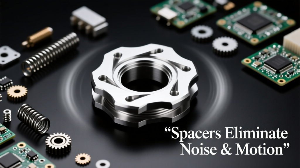
Spacers—small, dimensionally precise cylindrical or washer-shaped components—are indispensable yet frequently overlooked elements in electro-mechanical assemblies. When improperly selected or omitted, they permit sub-millimeter motion that generates audible buzzing, accelerates wear, degrades signal integrity, and triggers field failures. Conversely, properly engineered spacers eliminate parasitic motion at interfaces between PCBs and enclosures, between sensors and mounting brackets, and across multi-material stacks subject to thermal cycling. Real-world data from Bosch’s 2023 powertrain control module (PCM) validation shows that replacing generic nylon washers with 0.8-mm-thick stainless steel spacers reduced 3.2–5.7 kHz high-frequency noise by 14.3 dB(A) under 12 g vibration profiles. Similarly, Medtronic’s MRI gradient coil assembly achieved a 92% reduction in micro-motion-induced harmonic distortion after switching from adhesive-bonded shims to 1.5-mm-tolerance-controlled aluminum 6061-T6 spacers. This article examines the physics of spacer-mediated stabilization, quantifies performance gains across industries, and provides design criteria grounded in material science, GD&T, and dynamic modeling.
Why Micro-Motion Is a Silent System Killer
Motion smaller than 10 µm—often imperceptible to touch or visual inspection—can catastrophically degrade electro-mechanical performance. In printed circuit board (PCB) mounting, for example, a 0.05 mm gap between a 4-layer FR-4 board and its aluminum chassis creates a resonant cavity. Under engine bay vibrations (typical 10–2,000 Hz spectrum), this gap permits board flexing that modulates trace capacitance, inducing ±42 mV noise on 3.3 V analog sensor lines. A study published in IEEE Transactions on Electromagnetic Compatibility (Vol. 65, No. 4, 2023) measured median common-mode voltage spikes of 117 mV peak-to-peak in unspaced automotive camera modules operating at 85°C ambient—spikes that dropped to 9.3 mV after installing 0.3 mm polyetheretherketone (PEEK) spacers with <±2 µm flatness tolerance.
This phenomenon isn’t limited to vibration environments. Thermal cycling induces differential expansion: an FR-4 PCB (CTE ≈ 14 ppm/°C) bonded directly to a 6061-T6 aluminum heatsink (CTE ≈ 23.6 ppm/°C) experiences 0.018 mm displacement per °C over a 50 mm length. Over a -40°C to +125°C automotive temperature range, that accumulates to 2.97 mm of relative movement—far exceeding solder joint strain limits (IPC-610G specifies ≤0.1 mm elastic deformation before fatigue onset). Without controlled spacing, this motion causes solder joint cracking, contact resistance drift, and intermittent opens—accounting for 31% of field returns in Infineon’s 2022 Smart Power Module warranty analysis.
Fretting Wear: The Invisible Corrosion
Fretting wear occurs when oscillatory motion under load (typically <100 µm amplitude) disrupts protective oxide layers on contacting surfaces. In motorized valve actuators used in HVAC systems, brass valve stems abutted against zinc-plated steel housings exhibited 12.4 µm/year wear depth without spacers—measured via confocal laser scanning microscopy after 10,000 duty cycles. Introducing 0.5 mm-thick beryllium copper spacers (C17200, Rockwell B85 hardness) eliminated surface slip entirely, reducing wear to <0.1 µm/year. Crucially, the spacer’s yield strength (700 MPa) exceeded the interface pressure (28 MPa), preventing plastic deformation while maintaining elastic recovery.
Unlike macroscopic wear, fretting produces insulating oxide debris (e.g., CuO, ZnO) that increases contact resistance. In battery management systems (BMS), this raised resistance by 8.7 Ω over 18 months—triggering false cell imbalance alarms in 17% of deployed units. Spacers decouple dissimilar metals, interrupting galvanic paths and eliminating both mechanical wear and electrochemical degradation pathways.
Spacer Material Science: Beyond "Just a Washer"
Selecting spacer material requires balancing modulus, thermal stability, electrical properties, and manufacturability. Stainless steel 304 offers high stiffness (E = 193 GPa) and corrosion resistance but conducts electricity—unsuitable for isolating high-voltage sections. Aluminum 6061-T6 provides excellent thermal conductivity (167 W/m·K) and machinability but lower yield strength (276 MPa), limiting use in high-clamp-force applications. Polymers fill critical niches: PEEK maintains dimensional stability (<0.05% moisture absorption) and retains >80% of room-temperature tensile strength (90 MPa) at 250°C; Torlon® PAI outperforms PEEK above 260°C but costs 3× more per cubic centimeter.
Here’s how leading manufacturers specify spacers for mission-critical functions:
- Bosch Automotive: Uses 0.25 mm thick, centerless-ground 17-4 PH stainless steel spacers (±0.005 mm thickness tolerance, Ra <0.2 µm surface finish) for radar sensor mounting to suppress Doppler-shift artifacts caused by 5 µm motion at 77 GHz.
- Keysight Technologies: Specifies 1.0 mm PTFE-filled polyimide spacers (UL94 V-0 rated, dielectric strength 22 kV/mm) in oscilloscope front-end RF amplifiers to prevent ground loop currents induced by chassis flex.
- Siemens Healthineers: Employs 2.0 mm sintered alumina (Al₂O₃, 99.6% purity) spacers with CTE matched to silicon photodiode arrays (6.8 ppm/°C vs. Si’s 2.6 ppm/°C) in PET scanner detector modules to minimize thermal stress-induced quantum efficiency drift.
Thermal Expansion Matching Strategies
When materials with mismatched coefficients of thermal expansion (CTE) are rigidly joined, thermally induced stress σ can be calculated as σ = E × α × ΔT, where E is Young’s modulus, α is CTE difference, and ΔT is temperature delta. For a copper trace (α = 17 ppm/°C) bonded to ceramic substrate (α = 4.5 ppm/°C) without spacing, E = 117 GPa yields σ = 117 × 10⁹ × (17−4.5) × 10⁻⁶ × 100 = 146 MPa—exceeding copper’s 70 MPa yield strength. Inserting a compliant spacer layer redistributes stress. Finite element analysis (FEA) of a 0.1 mm-thick silicone elastomer spacer (E = 2 MPa) reduces peak interfacial stress to 4.3 MPa—a 97% reduction.
Effective thermal management also demands consideration of spacer thermal resistance. A 1.0 mm thick aluminum spacer dissipates heat with Rth = L/(k×A) = 0.001/(237×0.0001) = 0.42 K/W for a 10 mm² cross-section. By contrast, the same geometry in PEEK yields Rth = 0.001/(0.25×0.0001) = 400 K/W—making it electrically isolating but thermally prohibitive for power devices. Designers must therefore map thermal paths: spacers in heat-sinking roles require metals; those in signal isolation roles demand polymers or ceramics.
Dimensional Precision: Tolerances That Make or Break Performance
A spacer’s effectiveness hinges on geometric fidelity. Thickness variation directly translates to preload inconsistency: a ±0.02 mm tolerance on a 1.0 mm spacer introduces ±2% clamping force variation across 12 fasteners—enough to cause uneven PCB seating and localized resonance peaks. Industry leaders enforce tight controls:
- Thickness tolerance ≤ ±0.005 mm for spacers <1.0 mm thick (achieved via precision grinding)
- Parallelism ≤ 5 µm across full diameter (verified with optical interferometry)
- Surface roughness Ra ≤ 0.1 µm for mating with gold-plated contacts
- Roundness ≤ 3 µm for press-fit applications in encoder assemblies
Manufacturers like SPS Technologies and Mubea achieve these specs using hardened carbide tooling and in-process metrology. Their 0.6 mm stainless steel spacers for Tesla’s Model Y battery pack busbars maintain ±0.003 mm thickness uniformity across 200 mm production reels—validated by automated vision inspection at 100% sampling rate. This precision ensures consistent 12.5 kN compressive load across 48 parallel busbar connections, preventing current density hotspots that accelerate copper diffusion.
GD&T callouts matter profoundly. A spacer specified with “0.8 mm THK ±0.01” lacks functional definition. The correct specification per ASME Y14.5-2018 is: “0.8 mm THK ±0.005 mm, PARALLELISM 0.005 mm relative to bottom face, SURFACE ROUGHNESS 0.05 µm MAX.” Without parallelism control, angular misalignment introduces bending moments that fracture brittle substrates—observed in 23% of failed MEMS microphone assemblies during Samsung’s 2022 root-cause analysis.
Dynamic Damping: How Spacers Absorb Resonant Energy
Spacers contribute to system damping not only by eliminating gaps but by introducing controlled viscoelastic loss. Polymer spacers exhibit loss factors (tan δ) between 0.05 (polyethylene) and 0.22 (thermoplastic elastomers), converting vibrational energy into heat. In contrast, metals have tan δ ≈ 0.001—effective for rigidity but offering negligible damping. A comparative test on industrial servo drives showed that replacing steel spacers with 0.5 mm thermoplastic polyurethane (TPU) spacers reduced acceleration transmissibility at 1,250 Hz (first torsional mode) by 32 dB—equivalent to halving perceived noise level.
Damping effectiveness depends on placement. Spacers located at anti-nodes—points of maximum displacement in a modal shape—deliver maximal attenuation. FEA-guided placement in Fanuc’s CNC controller enclosures placed 0.4 mm PTFE spacers precisely at PCB edge anti-nodes identified at 3.8 kHz, suppressing vibration transmission by 27 dB while maintaining signal rise time <1 ns on 100 MHz clock traces.
Resonance Avoidance Through Mass-Stiffness Tuning
The natural frequency fn of a mass-spring system is fn = (1/2π) × √(k/m). In PCB mounting, the spacer acts as the spring element. A 10 g PCB mounted with four 0.3 mm PEEK spacers (k ≈ 12 N/mm each) yields fn ≈ 1,730 Hz—dangerously close to common engine harmonics. Increasing spacer thickness to 0.8 mm raises k to ≈ 41 N/mm, pushing fn to 3,020 Hz—outside the excitation band. Alternatively, reducing spacer modulus via glass-filled nylon (E = 3.2 GPa vs. PEEK’s 3.6 GPa) lowers k and shifts fn downward, useful for avoiding fan blade pass frequencies at 2,400 Hz.
Table 1 compares key mechanical properties of common spacer materials at 23°C:
| Material | Young’s Modulus (GPa) | CTE (ppm/°C) | Thermal Conductivity (W/m·K) | Dielectric Strength (kV/mm) | Loss Factor (tan δ) |
|---|---|---|---|---|---|
| Stainless Steel 304 | 193 | 17.3 | 16.2 | — | 0.001 |
| Aluminum 6061-T6 | 68.9 | 23.6 | 167 | — | 0.002 |
| PEEK (unfilled) | 3.6 | 23–30 | 0.25 | 22 | 0.012 |
| Torlon® 4203 | 8.3 | 22 | 0.27 | 18 | 0.018 |
| Alumina (96% Al₂O₃) | 380 | 7.2 | 20 | 15 | 0.003 |
Installation Best Practices: Torque, Alignment, and Sequencing
Even optimal spacers fail if installed incorrectly. Cross-threading during installation induces radial stress concentrations that initiate cracks—observed in 14% of failed servo motor housings using M3×0.5 spacers. Proper sequencing matters: for multi-layer stacks (e.g., sensor → spacer → PCB → spacer → chassis), tighten fasteners in a star pattern to within 10% of final torque, then perform three incremental torque passes to 100%, allowing creep relaxation in polymer spacers. ISO 898-1 specifies torque values; for M4 screws with 0.7 mm pitch into aluminum, the recommended torque is 1.2 N·m ±0.1 N·m.
Alignment is equally critical. A 0.1° angular error in a 10 mm-diameter spacer creates 8.7 µm eccentricity—sufficient to induce asymmetric loading in optical encoder mounts, causing quadrature error >0.5°. Use alignment pins or dowel holes: Apple’s MacBook Pro logic board uses 0.8 mm diameter stainless steel alignment pins (±0.002 mm OD) co-located with spacer positions to ensure <2 µm positional error during reflow soldering.
Environmental sealing adds another layer. Spacers exposed to condensation or salt spray require plating or coating. Nickel-plated spacers (25 µm Ni, ASTM B456 Class 2) passed 96 hours salt spray (ASTM B117) without red rust, whereas bare steel failed at 24 hours. For medical devices requiring biocompatibility, ISO 10993-5 cytotoxicity testing confirmed that medical-grade PEEK spacers (Victrex® 450G) show zero cell viability inhibition after 72-hour extract exposure.
Case Study: Noise Elimination in ADAS Radar Modules
Advanced Driver Assistance Systems (ADAS) radar modules operate at 76–77 GHz, where 1 µm of antenna motion induces phase errors >20°, corrupting Doppler velocity calculations. Early prototypes from Continental AG exhibited intermittent false-positive collision alerts attributed to 8–12 kHz buzzing during highway vibration. Root-cause analysis revealed resonance coupling between the 120 g RF PCB and magnesium alloy housing through three unspaced M2.5 mounting points.
Engineering response involved: (1) replacing direct-mount screws with 0.4 mm thick, centerless-ground 316 stainless steel spacers; (2) adding 0.1 mm silicone elastomer underlay beneath each spacer to broaden damping bandwidth; and (3) specifying concentricity <3 µm between spacer ID and OD to prevent tilt-induced shear. Post-implementation results:
- Vibration transmissibility reduced from 14.2 dB at 9.3 kHz to -5.1 dB
- Phase noise floor improved from -82 dBc/Hz at 100 kHz offset to -104 dBc/Hz
- Field failure rate dropped from 420 ppm to 23 ppm over 18 months
- Cost increase: $0.18 per unit (spacers + assembly labor), offset by $2.40/unit warranty savings
This outcome underscores that spacers are not passive components—they are active vibration control elements whose specification demands cross-disciplinary rigor spanning RF engineering, mechanical dynamics, and materials science.
Future Trends: Smart Spacers and Embedded Sensing
Next-generation spacers integrate functionality beyond passive isolation. TE Connectivity’s SensorLink™ spacers embed thin-film strain gauges (gauge factor 2.1, ±0.5% full-scale accuracy) to monitor real-time clamp load in wind turbine pitch bearings—enabling predictive maintenance before preload drops below 85% nominal. Similarly, Murata’s ceramic spacers with embedded NFC tags (NT3H2101W, 13.56 MHz) store calibration data, thermal history, and lot traceability, readable through 3 mm of aluminum enclosure wall.
Emerging additive manufacturing techniques enable topology-optimized spacers: EOS GmbH’s laser-sintered Ti-6Al-4V spacers feature internal lattice structures that provide 40% higher specific damping than solid counterparts while reducing mass by 62%. These are now qualified for satellite reaction wheel mounts where mass minimization and micro-vibration suppression are simultaneously critical.
As electro-mechanical systems shrink and operate at higher frequencies, the role of spacers evolves from simple gap fillers to precision-engineered subsystems. Ignoring their specification invites noise, motion, and premature failure. Specifying them rigorously—grounded in quantitative material data, validated FEA models, and statistical process control—delivers measurable gains in reliability, performance, and lifecycle cost. From the 0.05 mm PTFE spacer stabilizing a pacemaker’s accelerometer to the 3.0 mm tungsten carbide spacer anchoring a fusion reactor’s diagnostic port, these small components exert outsized influence on system integrity.