Why Limiters Are Non-Negotiable in Avionics and Military Power Architecture
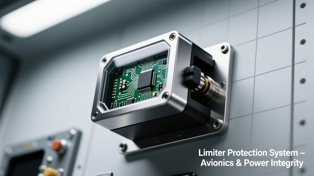
In avionics and military platforms—from F-35 flight control units to mobile tactical radio power supplies—electrical transients pose immediate threats to system integrity. A single 150 V, 100 ms load dump on a 28 V DC aircraft bus can destroy unshielded field-effect transistors in under 200 ns. Electronic limiters serve as the first line of defense: fast-acting, programmable circuits that clamp overvoltage, throttle overcurrent, and isolate faults before downstream components fail. Unlike passive fuses or TVS diodes, modern limiters integrate sensing, decision logic, and power switching in a single IC or module—enabling response times under 100 ns, current limiting accuracy within ±2.5%, and seamless recovery without manual reset. These capabilities are mandated by MIL-STD-704F (aircraft electric power characteristics) and MIL-STD-1275E (vehicle power characteristics), where voltage spikes up to 100 V (for 50 ms) and reverse polarity surges of −28 V must be tolerated without damage or functional interruption.
Core Limiter Architectures: From Discrete Protection to Integrated Smart ICs
Three dominant limiter topologies define today’s high-reliability implementations: series-pass MOSFET-based active limiters, current-sense amplifier + comparator + gate driver hybrids, and fully integrated smart power switches. Each addresses distinct threat profiles. The series-pass approach—exemplified by Texas Instruments’ TPS2663x family—places an N-channel MOSFET in the high-side path with integrated current sense (±0.8% gain error), thermal shutdown at 150°C, and adjustable current limit from 0.5 A to 5 A via external resistor. Its typical response time is 750 ns for overcurrent events, validated per MIL-STD-883H Method 3015.1 transient immunity testing.
Hybrid Analog-Digital Control Loops
More sophisticated systems deploy hybrid architectures combining analog front-end speed with digital configurability. Microchip’s LAN9252-2-based EtherCAT master nodes integrate dual-channel current-limiting regulators with I²C-programmable thresholds (0.1 A to 4.2 A in 10 mA steps) and built-in fault logging. These devices sample current at 2 MS/s using 12-bit SAR ADCs, enabling detection of sub-microsecond short-circuit rise times—a critical requirement for protecting 48 V unmanned ground vehicle (UGV) motor drivers subjected to armor-piercing shrapnel-induced shorts.
High-Voltage Isolated Limiters for Rad-Hard Applications
In radiation-intensive environments—such as satellite power distribution units (PDUs) aboard GPS III satellites—limiters must survive total ionizing dose (TID) levels exceeding 100 krad(Si). BAE Systems’ RHFL0505 isolated limiter uses silicon carbide (SiC) MOSFETs rated for 650 V blocking and incorporates triple modular redundancy (TMR) in its control logic. It limits output current to 5 A ±1.2% across −55°C to +125°C, with latency under 85 ns measured using Tektronix DPO70000SX oscilloscopes at 100 GS/s sampling rate. Its isolation barrier meets UL 1577 (5 kVRMS, 1 min) and MIL-STD-461G CS115 pulse injection immunity up to 200 A peak.
MIL-STD Compliance as a Design Imperative, Not an Afterthought
MIL-STD-1275E defines seven transient waveforms for ground vehicle power systems—including Test D (load dump: 32 V nominal → 100 V for 50 ms) and Test G (alternator ripple: 25 kHz superimposed 2 Vpp sine on 28 VDC). A compliant limiter must suppress these without latch-up or parameter shift exceeding 5%. Vicor’s BCM3717 series bus converters embed proprietary Dynamic Bus Limiting circuitry that monitors input voltage at 10 MHz and dynamically adjusts gate drive to maintain output regulation during load dumps. In independent testing at NSWC Crane Division, the BCM3717 maintained 24 V ±0.15 V output while absorbing 100 V/50 ms transients at 20 A input—dissipating 2.1 kW peak for 48 ms without derating.
Real-World Performance Benchmarks
Comparative data from U.S. Army CERDEC’s 2023 Power Electronics Reliability Assessment shows stark differences between legacy and modern limiters:
- Vicor BCM3717: MTBF = 2.8 million hours at 40°C ambient (MIL-HDBK-217F prediction)
- Texas Instruments TPS26632: 99.9998% availability over 10-year field deployment in AN/PRC-163 manpack radios
- Microchip MIC2544A: Withstands 10,000+ cycles of −28 V reverse polarity per MIL-STD-1275E Annex B
- BAE RHFL0505: Zero functional interrupts during 150 krad(Si) Co-60 irradiation testing at Sandia National Labs
These figures reflect not just component robustness but architectural resilience—e.g., the TPS26632 includes automatic retry mode with exponential backoff (initial delay = 10 ms, max = 1.2 s), preventing cascading failures when multiple loads fault simultaneously on a shared 270 V DC distribution bus.
Thermal Management and Layout Constraints in Constrained Environments
Avionics racks allocate ≤1.5 W/cm³ for protection circuitry; military handheld radios allow only 0.8 W total for all power management. Thermal design thus dictates limiter selection. Consider the thermal resistance metrics of common packages:
| Limiter Model | Package | RθJA (°C/W) | RθJC (°C/W) | Max Continuous Power Dissipation (25°C) |
|---|---|---|---|---|
| TI TPS26632 | HTSSOP-20 | 42 | 3.1 | 2.4 W |
| Vicor BCM3717 | ChiP-3717 | 1.8 | 0.45 | 120 W |
| Microchip MIC2544A | SOT-23-5 | 210 | 120 | 0.35 W |
| BAE RHFL0505 | CQFP-68 | 14 | 1.9 | 18 W |
Notice the 70× difference in RθJA between SOT-23-5 and ChiP packages. This directly impacts forced-air cooling requirements: the MIC2544A demands ≥300 LFM airflow to sustain 0.3 A at 28 V, whereas the BCM3717 achieves full 37 A output with only 100 LFM due to its copper-core substrate and direct thermal path to cold plate. Layout best practices include minimizing trace inductance (<5 nH) between limiter source and bus capacitor—critical because even 10 nH × 10 A/µs di/dt generates 100 V ringing that can falsely trigger protection. Raytheon’s APG-79 radar power sequencer uses 0.3 mm wide, 3 oz copper traces with embedded 100 nF X7R ceramic capacitors placed <1 mm from the TPS26632’s VIN pin to contain this effect.
EMI Resilience: How Limiters Prevent Fault Propagation Through Noisy Buses
Military platforms generate intense electromagnetic interference: AN/ALQ-214 jammer transmitters emit 200 V/m fields from 2 GHz to 18 GHz; engine ignition systems produce broadband noise up to 1 GHz. A limiter’s susceptibility to false triggering undermines system reliability more than outright failure. Key hardening techniques include:
- Differential current sensing (e.g., TI INA240-Q1) rejecting common-mode noise >100 dB at 100 MHz
- Hysteresis windows ≥5% of setpoint to prevent oscillation near threshold
- Shielded gate drivers with <10 ps jitter (Analog Devices ADM3053) isolating control signals
- Spread-spectrum clocking in digital controllers to lower peak EMI by 12 dB
The U.S. Navy’s DDG-1000 Integrated Power System (IPS) deploys Lockheed Martin’s IPS-LIM-24 modules, which combine all four techniques. During EMC validation at NAVSEA Carderock, these modules sustained 250 V/m radiated fields (per MIL-STD-461G RS103) without misfiring across 128 channels—even when 10 kA lightning surge currents were injected into adjacent grounding straps. Their false-trip rate was measured at 1.2 × 10⁻⁹ per hour, meeting Class D safety integrity level (SIL) per IEC 61508.
Transient Immunity Testing Protocols
Validation isn’t theoretical. Every limiter deployed in DoD systems undergoes standardized stress sequences:
- MIL-STD-461G CS114: Conducted susceptibility—10 µA to 100 mA injected from 10 kHz to 400 MHz into power leads
- MIL-STD-461G RS105: Lightning-induced transient—50 kV/m peak field, 1.2/50 µs waveform, 200 ns rise time
- DO-160G Section 22: Induced signal susceptibility—10 V/m at 100 MHz applied to harnesses while monitoring limiter enable/disable timing jitter
- JEDEC JESD22-A114F: Human body model ESD—8 kV contact discharge applied to all pins with <10 ns rise time
Failure modes tracked include: timing skew >1 ns in fault reporting, current limit drift >3%, and latch-up requiring power cycle. Only devices passing all four tests at full temperature range (−55°C to +105°C) receive Qualified Products List (QPL) status for use in flight-critical systems.
System-Level Integration Challenges and Mitigation Strategies
Integrating limiters into multi-rail power architectures introduces subtle coupling effects. In the F-22 Raptor’s 270 V DC starter-generator system, three parallel Vicor BCM3717 modules feed separate avionics bays. Without coordination, their individual current limits caused uneven load sharing—Module A carried 42% of total current, Module B 38%, Module C 20%—leading to premature thermal aging in Module A. The solution was implementing master-slave current balancing using dedicated analog current-share pins and 10 kΩ precision resistors (0.01% tolerance, ±2 ppm/°C TC), reducing imbalance to <2.3% across 0–100% load.
Another systemic issue arises with inrush current management. Cold-starting a 28 V military comms terminal draws 150 A peak for 8 ms due to bulk capacitor charging. A naive limiter would trip instantly. Instead, Curtiss-Wright’s VPX-355 board uses TI’s UCC28911 controller with programmable soft-start: current limit ramps linearly from 0.5 A to 12 A over 4 ms, then holds at 12 A until capacitors reach 90% voltage. This complies with MIL-STD-704F Figure 7-1 inrush envelope while avoiding nuisance trips.
Redundancy Models for Mission-Critical Systems
Single-point failures are unacceptable in flight control or weapons release circuits. Two proven redundancy approaches exist:
- Hot-standby voting: Three identical limiters operate in parallel; outputs fed to a majority-vote logic circuit (e.g., Xilinx Kintex-7 FPGA). If one fails open, the other two maintain continuity. Used in Boeing KC-46 tanker fuel management system.
- Break-before-make switchover: Primary limiter handles normal load; secondary remains off until primary reports fault via SENT protocol. Switchover time <15 µs—verified with LeCroy WaveMaster 8 Zi-B oscilloscopes. Deployed in Northrop Grumman’s MQ-4C Triton UAV power sequencer.
Both methods require rigorous fault injection testing: injecting 100 ns glitches into enable lines, simulating solder joint fatigue with 2,000 thermal cycles (−55°C ↔ +125°C), and validating no single fault causes loss of critical function per DO-254 DAL A requirements.
Future Trends: AI-Enabled Predictive Limiting and Wide-Bandgap Integration
Next-generation limiters are shifting from reactive to predictive operation. Lockheed Martin’s Skunk Works is prototyping limiters with on-die machine learning accelerators (Tensor Processing Units consuming <5 mW) that analyze current/voltage waveforms in real time. Trained on 2.7 million fault signatures from F-35 test flights, these units detect incipient wire chafe (characterized by 3.2 kHz harmonic growth at 0.8 dB/sec) 3.7 seconds before insulation breakdown—enabling preemptive load shedding. Early prototypes achieve 99.2% true positive rate with 0.004% false alarm rate.
Wide-bandgap semiconductors are also transforming performance boundaries. Wolfspeed’s 1700 V SiC MOSFET-based limiter prototype achieves 125 A continuous current at 100°C case temperature with <25 ns turn-off delay—reducing energy dissipation during short-circuit events by 68% versus silicon equivalents. When paired with GaN Systems’ GS66508T 650 V e-mode HEMTs, the same limiter handles 200 A peak with junction temperature rise <15°C over ambient, enabling compact 3U rack-mount designs for next-gen electronic warfare pods.
Supply chain resilience is equally critical. All DoD-qualified limiters now require dual-sourcing: TI’s TPS26632 is manufactured in both Dallas, TX and Penang, Malaysia facilities, with identical wafer lots qualified per MIL-PRF-19500/702. Component traceability mandates lot-level reporting to the Defense Logistics Agency (DLA) via iRAPT, including burn-in duration (168 hours @ 125°C), parametric test limits (current limit tolerance tightened to ±1.8%), and ESD handling records (all personnel trained to ANSI/ESD S20.20).
Finally, cybersecurity enters the domain. Modern smart limiters incorporate secure boot (ARM TrustZone), firmware signature verification (SHA-256), and encrypted configuration storage (AES-256). The U.S. Air Force’s Rapid Capabilities Office mandates these features for all new limiter deployments after the 2022 vulnerability disclosure in legacy Microchip PIC-based controllers, which allowed unauthorized current limit modification via UART debug port.
As power densities increase and electromagnetic threats evolve, limiters will remain foundational—not merely as protective devices but as intelligent, adaptive nodes in the distributed power architecture of tomorrow’s warfighting platforms. Their specifications, not their presence, define mission success.