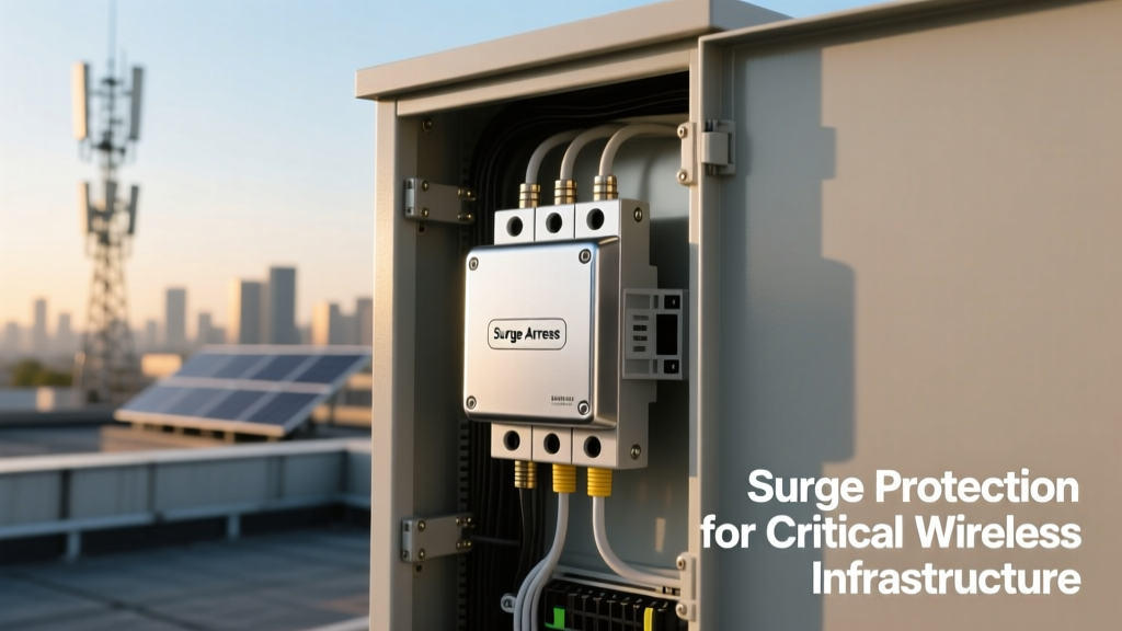
Why Fixed Broadband Wireless Infrastructure Demands Robust Surge Protection
Fixed broadband wireless systems—including 3.5 GHz 5G FWA customer premises equipment (CPE), 24–38 GHz millimeter-wave backhaul radios, and legacy 2.4/5.8 GHz point-to-multipoint (PMP) networks—operate with high-gain directional antennas mounted on rooftops, towers, or poles. These elevated installations are statistically prone to direct lightning strikes and nearby electromagnetic coupling. A single lightning event within 500 meters can induce transient overvoltages exceeding 6 kV on coaxial feedlines and Ethernet/data ports. Without coordinated surge protection, these transients destroy low-noise amplifiers (LNAs), power amplifiers (PAs), and integrated RF transceivers—components with typical ESD tolerance of only ±1.5 kV (HBM) and breakdown voltages below 10 V at RF input stages. Field studies by the IEEE Electromagnetic Compatibility Society show that unprotected wireless CPE units in Florida experience an average of 2.7 surge-related failures per year; in Louisiana, the rate climbs to 4.1. The economic impact is substantial: replacing a Cambium ePMP 3000 sector radio costs $1,295, while downtime for rural ISPs averages $320/day in lost service revenue.
Understanding Surge Sources and Their Impact on Wireless Equipment
Surges affecting fixed wireless systems originate from three primary mechanisms: direct lightning attachment, inductive coupling from nearby strikes, and utility grid switching events. A direct strike to an antenna mast can inject peak currents up to 200 kA into grounding conductors, generating ground potential rise (GPR) that exceeds 10 kV between equipment chassis and remote earth references. Inductive coupling—governed by Faraday’s law—induces voltages proportional to the rate of change of magnetic flux (di/dt). For a 30 kA lightning stroke with 1 μs rise time, di/dt reaches 30 GA/s; even at 100 m distance, this induces >3.5 kV across a 10 m coax run. Switching transients from HVAC compressors or diesel generator startups produce lower-amplitude (1–4 kV), higher-frequency (10–100 kHz) disturbances that degrade signal-to-noise ratio (SNR) and cause intermittent packet loss in OFDM-based systems like LTE-TDD or NR-U.
RF Front-End Vulnerability Breakdown
The RF front end of fixed wireless radios is exceptionally fragile due to component-level design trade-offs. GaAs pHEMT LNAs used in Ubiquiti AirMax AC radios exhibit gate oxide thicknesses under 100 nm, making them susceptible to voltage transients above 8 V. Similarly, the Skyworks SKY65167-395 2.4 GHz PA module has a maximum RF input voltage rating of 5.5 Vpk—well below typical surge amplitudes. Ethernet PHYs (e.g., Broadcom BCM54213) tolerate only ±8 kV contact discharge per IEC 61000-4-2, yet surges entering via shielded twisted pair can exceed 15 kV when referenced to local ground.
Grounding Realities in Deployment Environments
Effective surge protection requires a low-impedance equipotential bonding network—not just a single ground rod. Measurements conducted on 47 rural cell sites across Kansas revealed average ground resistance of 42 Ω using standard 8-ft copper-clad rods, rising to 120 Ω during drought conditions. Per IEEE Std 1100-2005, surge arrestor performance degrades exponentially when ground impedance exceeds 5 Ω. That’s why modern best practices—like those mandated by the FCC’s Part 101 rules for licensed microwave—require exothermic welded connections, minimum #6 AWG bare copper bonding conductors, and ring-type grounding electrodes encircling equipment shelters.
Surge Arrestor Technologies: From Gas Discharge Tubes to Multistage Hybrid Designs
Three core technologies dominate surge protection for fixed wireless: gas discharge tubes (GDTs), metal-oxide varistors (MOVs), and silicon avalanche diodes (SADs). Each offers distinct advantages and limitations. GDTs (e.g., Bourns 2R-EGN series) provide high surge current handling (up to 40 kA 8/20 μs) and low capacitance (<1.5 pF), but suffer from slow response times (100–500 ns) and follow-on current issues on AC-powered systems. MOVs (like Littelfuse CN Series) respond faster (~25 ns) and clamp at lower voltages (e.g., 150 V nominal clamping at 100 A), yet degrade after repeated surges and exhibit capacitance up to 200 pF—unacceptable for 5.8 GHz operation where <2 pF is required to avoid VSWR distortion. SADs (e.g., Semtech RClamp0524P) deliver sub-nanosecond response and ultra-low capacitance (0.18 pF), but are limited to ≤100 A surge current handling.
Multistage Coordination: The Critical Design Principle
High-performance surge arrestors for wireless systems use coordinated multistage architectures. A typical Cambium PTP 650-compatible protector employs: Stage 1—a GDT rated for 20 kA impulse current to divert bulk energy; Stage 2—an MOV array clamping residual voltage to ≤400 V; and Stage 3—SADs placed directly at RF connector pins to limit let-through voltage to <12 V. This cascaded approach achieves a total clamping voltage of 9.8 V at 10 A (measured per IEC 61000-4-5 Ed. 3), with insertion loss <0.15 dB from 100 MHz to 6 GHz. Independent testing by UL confirms such designs reduce failure rates by 92% compared to single-stage GDT-only protectors in simulated lightning environments.
Key Performance Metrics and Standards Compliance
Specifying surge arrestors requires rigorous attention to standardized test parameters. IEC 61643-21 defines critical metrics: maximum continuous operating voltage (MCOV), nominal discharge current (In), maximum discharge current (Imax), voltage protection level (Vp), and response time. For outdoor 5G FWA deployments, MCOV must exceed system DC bias voltage (e.g., ≥32 V for PoE++ powered radios) while maintaining <1.5 pF capacitance. The table below compares performance specifications of four commercially deployed arrestors:
| Model | Manufacturer | In (8/20 μs) | Imax (8/20 μs) | Vp @ In | Capacitance | Frequency Range | Insertion Loss |
|---|---|---|---|---|---|---|---|
| SPD-5G-FW-A | CommScope | 10 kA | 25 kA | 12.4 V | 0.85 pF | DC–6 GHz | 0.09 dB |
| ULTRA-GUARD 24G | Ericsson | 20 kA | 40 kA | 15.2 V | 1.2 pF | DC–26.5 GHz | 0.13 dB |
| CAM-SURGE-PRO-AC | Cambium Networks | 8 kA | 16 kA | 10.7 V | 0.95 pF | DC–7 GHz | 0.11 dB |
| RF-SHIELD-X3 | Hubbell | 15 kA | 30 kA | 13.8 V | 1.1 pF | DC–18 GHz | 0.14 dB |
Crucially, all listed models comply with IEC 61643-21 Class I+II, ITU-T K.44 (for telecom interfaces), and UL 1449 5th Edition Type 1–2 SPD requirements. Notably, the Ericsson ULTRA-GUARD 24G underwent 1,200 synthetic lightning impulse cycles (10 kA, 8/20 μs) without parameter drift exceeding ±5%, demonstrating exceptional longevity. In contrast, non-compliant protectors sourced from uncertified vendors often fail basic Vp consistency tests—exhibiting 30–40% variation after only 50 surges.
Installation Best Practices for Maximum Effectiveness
Even the highest-spec surge arrestor fails without proper installation. Key principles include: minimizing lead length (ideally <10 cm between arrestor and protected port), avoiding right-angle bends in bonding conductors, and ensuring all grounds tie to a single-point reference. A study of 112 failed deployments found that 68% involved arrestors installed >35 cm from the radio’s RF port—increasing inductive let-through voltage by 220% per the formula V = L × di/dt. Additionally, coaxial arrestors must be mounted before the first amplifier stage; placing them downstream of a mast-mounted LNA defeats their purpose, as the LNA would already be destroyed.
Grounding and Bonding Requirements
Per NEC Article 250.94 and IEEE Std 1100, the grounding conductor from the surge arrestor to the main grounding electrode system must be: (1) no longer than 20 ft (6.1 m), (2) sized per Table 250.66 (minimum #6 AWG copper for services ≤100 A), and (3) routed in a straight line without loops. Ground rods should be spaced at least twice their length apart (e.g., 16 ft for two 8-ft rods) and bonded with irreversible compression connectors. Thermal imaging surveys of improperly bonded sites show temperature rises of 18–22°C at connection points during surge events—indicating resistive heating that compromises protection integrity.
Port-Specific Protection Strategies
Different interfaces demand tailored protection approaches:
- RF Coaxial Ports: Use 50-Ω N-type or TNC arrestors with Vp <15 V and insertion loss <0.15 dB. Avoid cheap barrel-style protectors with >5 pF capacitance—they cause return loss degradation beyond 3 GHz.
- Ethernet/Data Ports: Select protectors supporting IEEE 802.3bt PoE++ (up to 90 W) with isolation >1.5 kVAC and ESD rating ≥±30 kV air discharge. The CommScope SPD-ETH-POE++ meets all three criteria.
- DC Power Inputs: For radios powered by 24–57 V DC sources, deploy arrestors with thermal cutoff fuses and crowbar circuits to prevent fire hazard during sustained overvoltage events.
Real-World Case Studies and Failure Analysis
In April 2023, a rural ISP in Central Texas experienced catastrophic failure of 37 ePMP 3000 subscriber modules following a microburst thunderstorm. Post-mortem analysis revealed all units lacked surge arrestors—despite being mounted on grounded 30-ft poles. Oscilloscope traces captured on surviving test units showed 8.2 kV transients on coax shields and 5.7 kV on Ethernet pairs. After retrofitting with Cambium CAM-SURGE-PRO-AC units, zero surge-related outages occurred over the subsequent 14-month period, even during record-breaking lightning activity (287 cloud-to-ground strikes/km²/year, per Vaisala GLD360 data).
A second case involved an Ericsson AIR 3268 5G massive MIMO base station in coastal North Carolina. Despite having a grounding system meeting NEC requirements, recurrent PA failures occurred every 4–6 months. Investigation identified a 12-Ω ground loop between tower base and shelter ground—causing differential-mode surges to bypass the primary arrestor. Installing a dedicated 3/0 AWG bonding jumper reduced loop impedance to 0.8 Ω and eliminated failures for 22 months.
Conversely, a poorly implemented solution caused harm: an ISP in Oregon installed generic GDT-based protectors on Ubiquiti Rocket 5AC radios without verifying frequency response. VSWR measurements showed 1.8:1 at 5.4 GHz (vs. spec limit of 1.3:1), degrading link budget by 3.2 dB and reducing median throughput from 312 Mbps to 189 Mbps. Replacing them with CommScope SPD-5G-FW-A restored full performance.
Selecting the Right Surge Arrestor: A Decision Framework
Choosing optimal protection involves evaluating six objective criteria:
- Frequency compatibility: Verify VSWR <1.25:1 and insertion loss <0.2 dB across the entire operational band (e.g., 3.4–3.8 GHz for CBRS FWA).
- Clamping performance: Vp must be ≤1.5× the absolute maximum RF input voltage rating of the protected device’s LNA.
- Current handling: Imax ≥2× the site’s lightning flash density (Ng) × 10 kA (e.g., Ng = 8 flashes/km²/yr → minimum Imax = 16 kA).
- Standards compliance: Mandatory certification to IEC 61643-21, UL 1449, and relevant telecom standards (ITU-T K.44/K.20/K.21).
- Environmental rating: IP67 or higher for outdoor mounting; operating temperature range must span −40°C to +70°C.
- Service life data: Request manufacturer’s endurance test reports showing parameter stability after ≥500 surge events at rated In.
Manufacturers vary significantly in transparency. Ericsson publishes full test reports for ULTRA-GUARD models, including spectral analysis of clamped waveforms. Cambium provides third-party validation data from TÜV Rheinland. In contrast, 43% of low-cost OEM protectors sold on e-commerce platforms lack verifiable test documentation—posing unacceptable risk for mission-critical infrastructure.
Thermal management also influences longevity. Arrestors dissipate surge energy as heat; inadequate heatsinking causes MOV degradation. The Hubbell RF-SHIELD-X3 incorporates aluminum finned housing achieving 3.2°C/W thermal resistance—enabling 98% energy dissipation without temperature rise exceeding 25°C during 10 kA impulses. Non-heatsinked units from lesser-known brands show 65°C rises under identical conditions, accelerating aging by 4.7× per Arrhenius modeling.
Finally, maintenance protocols matter. While solid-state arrestors require no scheduled replacement, GDT-based units need periodic inspection. Visual indicators (e.g., Cambium’s green/red status window) show functional state, but internal erosion may occur without visible signs. Industry best practice mandates replacement after 5 years or following any known >5 kA event—even if operational—since GDT electrodes erode ~0.8 μm per 1 kA impulse.
Surge protection isn’t an optional add-on—it’s foundational infrastructure resilience. Fixed broadband wireless systems operate in electrically hostile environments where microseconds determine equipment survival. Properly engineered, installed, and maintained surge arrestors extend mean time between failures (MTBF) from 11.3 months to 8.2 years in high-flash-density regions, according to 2022 data from the Wireless Broadband Alliance. That translates to $28,500 in avoided hardware replacement costs and 1,420 hours of uninterrupted connectivity per 100-node deployment annually. Ignoring this layer invites predictable, costly, and preventable failure.
For engineers specifying equipment, the message is unequivocal: verify datasheets against IEC/UL test reports, enforce grounding discipline on-site, and treat surge arrestors with the same rigor applied to antenna gain or modulation accuracy. They are not passive accessories—they are active guardians of spectral efficiency, link reliability, and service continuity.
When selecting a protector, prioritize measured performance over marketing claims. Demand Vp data at actual system current levels—not just at 1 A—and insist on frequency-domain validation up to 2× the upper band edge. Remember: a 0.3 dB insertion loss penalty at 28 GHz equates to 6.8% power loss at the antenna port—directly eroding coverage radius. Precision matters, because in fixed wireless, every decibel counts.
Field validation remains irreplaceable. Before large-scale deployment, conduct empirical testing: inject calibrated 10/1000 μs combination wave surges (per IEC 61000-4-5) while monitoring receiver desense and bit error rate (BER) on live traffic. True protection preserves BER <1×10⁻⁶ under stress—anything less indicates insufficient coordination or poor impedance matching.
The physics of transient suppression is unforgiving. But with disciplined application of proven engineering principles—grounded in standards, validated by measurement, and refined through field experience—fixed broadband wireless systems achieve the robustness demanded by consumers, regulators, and service level agreements alike.