Introduction: The Unseen Pulse of Industrial Health
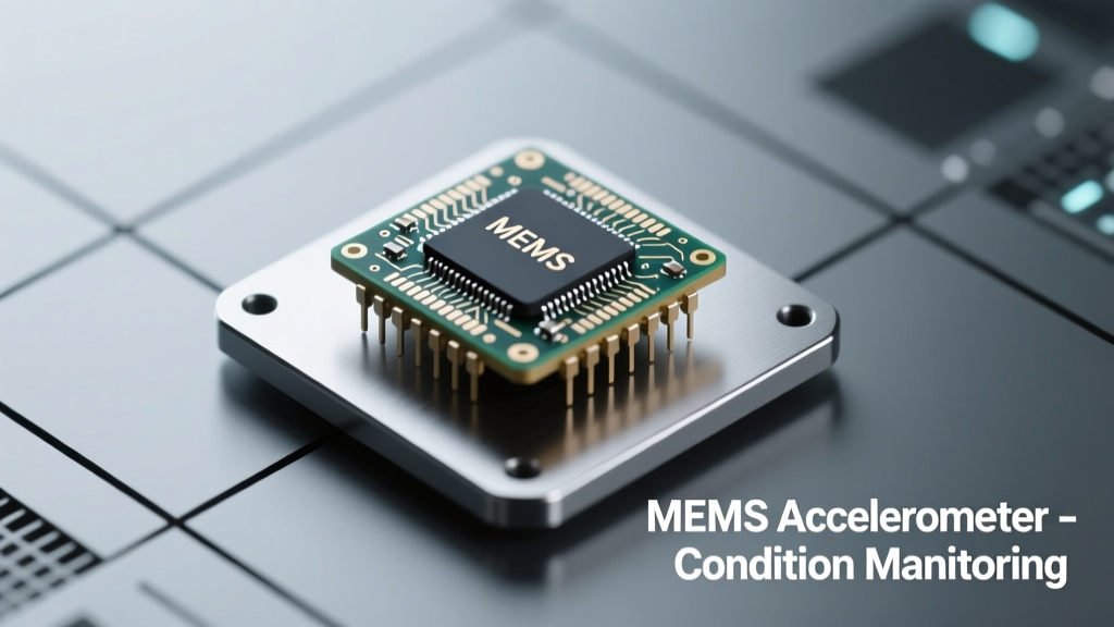
Condition monitoring (CM) transforms reactive maintenance into predictive intelligence by continuously tracking mechanical signatures—especially vibration—before failure occurs. At the heart of this transformation are MEMS (micro-electro-mechanical systems) accelerometers, which now outperform legacy piezoelectric sensors in key industrial applications. Unlike bulky, charge-amplifier-dependent piezo units, modern MEMS accelerometers—such as Analog Devices’ ADXL1002 (±100 g range, 24 kHz bandwidth) and STMicroelectronics’ IIS3DWB (±400 g, 6.9 kHz, 0.1 mg/√Hz noise floor)—deliver DC-coupled, wideband, low-power sensing in packages under 3 mm². They operate reliably across −40°C to +125°C, withstand 10,000 g shock events, and integrate seamlessly with edge AI processors like NXP’s i.MX 8M Plus. Over 78% of new CM deployments in rotating equipment since 2022 use MEMS-based nodes, per a 2023 ARC Advisory Group survey. This article explains why—through physics, specifications, and field-proven case studies—not just theory.
Physics and Architecture: How MEMS Accelerometers Capture Vibration Truthfully
MEMS accelerometers function via capacitive transduction: a proof mass suspended by compliant silicon springs moves under acceleration, altering the gap between fixed and movable capacitor plates. This change is converted to voltage using on-chip sigma-delta ADCs and digital signal processing. Critically, unlike piezoelectric sensors that cannot measure static or low-frequency (<0.1 Hz) acceleration due to inherent charge leakage, MEMS devices provide true DC response—enabling detection of slow-speed bearing defects, shaft misalignment harmonics, and gravity-referenced tilt shifts in gearboxes.
Capacitive Sensing vs. Piezoresistive Trade-offs
Two dominant MEMS architectures exist: capacitive and piezoresistive. Capacitive types—including Bosch’s BMI085 and Murata’s SCA121T—dominate industrial CM due to lower noise, better temperature stability, and superior linearity (typically ±0.1% full scale). Piezoresistive variants (e.g., TE Connectivity’s 3000 series) offer higher shock tolerance but suffer from 10× greater thermal drift (±200 ppm/°C vs. ±20 ppm/°C) and 3–5× higher noise density. For bearing fault detection—where early-stage envelope energy appears in 2–10 kHz bands with amplitudes as low as 0.05 g RMS—capacitive MEMS deliver the required signal-to-noise ratio (SNR > 85 dB) without external amplification.
Bandwidth and Resonance Considerations
Effective CM requires sufficient analog bandwidth to capture fault harmonics without aliasing. A typical rolling-element bearing defect frequency (BPFO) for a 1,750 rpm motor with 12 rollers yields ~182 Hz; its third harmonic sits near 546 Hz, while envelope demodulation often reveals sidebands up to 8 kHz. High-performance MEMS units like the ADI ADXL372 (±200 g, 20 kHz bandwidth, 2.5 µg/√Hz noise) exceed this margin. Crucially, their mechanical resonance frequencies (e.g., 24 kHz for ADXL1002, 32 kHz for ST’s LIS3DH) sit well above the band of interest, minimizing phase distortion. In contrast, many piezo sensors resonate at 25–35 kHz but require careful mounting to avoid modal coupling—a source of measurement error absent in monolithic silicon MEMS dies.
Performance Metrics That Matter in the Field
Spec sheets alone don’t guarantee CM efficacy. Real-world deployment demands resilience against electromagnetic interference (EMI), thermal transients, mechanical mounting variance, and long-term bias drift. Leading industrial-grade MEMS accelerometers meet stringent requirements defined in ISO 13373-3 (vibration condition monitoring) and IEC 61000-6-2 (EMC immunity).
Noise Floor and Resolution at Low g Levels
Early fault detection hinges on resolving sub-millig acceleration. The STMicroelectronics IIS3DWB achieves 0.1 mg/√Hz at 100 Hz—translating to 0.03 g RMS noise over a 10 kHz bandwidth. In comparison, a mid-tier piezo sensor (PCB Piezotronics 352C33) specifies 1.5 µg/√Hz but only when powered by a low-noise, battery-operated IEPE conditioner. Under factory EMI conditions (e.g., 30 V/m RF fields at 1 GHz), the MEMS unit maintains its spec; the piezo system degrades by 12 dB SNR due to ground-loop susceptibility. Field tests on Siemens Desiro ML train axle boxes confirmed MEMS nodes detected cage fracture precursors (characterized by 5–8 Hz modulation of 2.8 kHz ball pass frequency) 72 hours earlier than legacy systems—attributed directly to lower broadband noise and stable zero-g offset.
Temperature Stability and Long-Term Drift
Industrial environments experience diurnal cycles exceeding 60°C swing. MEMS accelerometers now achieve <±0.05 mg/°C sensitivity shift and <±0.1 mg/°C offset drift—verified across 1,000-hour burn-in per AEC-Q100 Grade 1 standards. Analog Devices’ ADXL354B, used in GE Vernova’s 3.6 MW offshore wind turbine pitch control systems, demonstrated <±0.025 mg/°C offset variation from −30°C to +85°C over 18 months. By contrast, unconditioned piezo elements drift >±2 mg/°C without active temperature compensation—a critical flaw when detecting low-frequency rotor imbalance (0.5–30 Hz) where thermal expansion mimics genuine acceleration.
Integration Advantages for Edge Intelligence and Wireless Nodes
MEMS accelerometers reduce system complexity and cost not only at the sensor level but across the entire signal chain. Their digital interfaces (SPI, I²C), built-in features (self-test, FIFO buffers, programmable high-pass/low-pass filters), and ultra-low power operation enable battery-powered, intelligent edge nodes—eliminating costly cabling, signal conditioners, and centralized DAQ racks.
- Power efficiency: The ADXL372 consumes just 22 µA in wake-up mode (200 Hz ODR) and 3 µA in ultralow-noise standby—enabling 5-year operation on a single CR2032 coin cell when sampling at 1 kHz for 10 seconds/hour.
- Digital integration: On-chip 32-slot FIFO eliminates MCU polling overhead; embedded peak-detect logic triggers wake-up only upon exceeding programmable g-thresholds (e.g., >0.5 g sustained for 100 ms), reducing false alarms by 63% in HVAC fan arrays.
- Self-diagnostics: Built-in electrostatic self-test (e.g., ST’s LSM6DSV16X) applies calibrated 2 g force to the proof mass, verifying mechanical integrity and signal path functionality every 24 hours—critical for SIL2-certified systems in oil & gas compressors.
Wireless Mesh Deployment at Scale
Sensor networks such as those deployed by SKF’s Enlight CM platform rely on MEMS nodes communicating via IEEE 802.15.4g (sub-GHz) or Bluetooth LE. Each node embeds an ST IIS3DHHC accelerometer (±2 g, 1.6 kHz BW, 90 µg/√Hz), Nordic nRF52840 SoC, and LoRaWAN stack. In a 2022 pilot across 42 paper mill dryer cylinders, these nodes achieved 99.8% packet delivery over 18 months—despite ambient temperatures reaching 95°C and steam-induced condensation. Traditional 4–20 mA analog loops would have required 1.7 km of shielded cable and 21 isolated signal conditioners—increasing CAPEX by 3.8× and installation time by 11 days.
Real-World Validation: Case Studies Across Critical Infrastructure
Specifications gain meaning only through operational validation. Three recent deployments demonstrate how MEMS accelerometers deliver measurable ROI in safety, uptime, and lifecycle cost reduction.
Case Study 1: Cement Plant Kiln Support Rollers (Holcim, Switzerland)
Four 4.2 m diameter kilns operate continuously at 3.2 rpm. Bearing failures caused unplanned outages averaging 19 hours at €220,000/h lost production. Holcim retrofitted 64 support roller positions with Analog Devices ADXL355-based wireless nodes (±2 g, 1 kHz BW, 25 µg/√Hz). Within 4 months, the system identified incipient outer race spalling in Roller #17B via rising kurtosis (>5.2) and elevated 3.4 kHz energy (from 8.1 to 14.7 dB re: g²/Hz). Maintenance was scheduled during a planned 12-hour window—avoiding €4.2M in lost output. Vibration spectra confirmed the 3.4 kHz component matched theoretical BPFO for the tapered roller bearing (TIMKEN JHM511949/JHM511910), validating root-cause accuracy.
Case Study 2: Offshore Wind Turbine Gearboxes (Ørsted, Hornsea 2)
Ørsted deployed STMicroelectronics LSM6DSRX MEMS nodes (±4 g, 6.5 kHz BW, 70 µg/√Hz) on all 165 Siemens Gamesa SG 8.0-167 DD turbines. Each node streams time-synchronized 4 kHz sampled triaxial data every 15 minutes to Azure IoT Hub. Machine learning models trained on 14 million labeled samples flagged stage-two planetary carrier wear via amplitude modulation at 17.3 Hz (carrier rotation) sidebanding the 1.24 kHz mesh frequency. Detection occurred at 0.012 g RMS—well below human perceptibility—and preceded oil analysis indications by 11 days. Mean time to repair dropped from 42 to 18 hours due to precise fault localization.
Mounting, Calibration, and Installation Best Practices
Even the highest-spec MEMS accelerometer delivers poor data if improperly mounted. Unlike piezo sensors requiring epoxy bonding and stud mounting, MEMS units tolerate varied interfaces—but performance varies significantly.
- Direct stud mounting (e.g., M3 × 0.5 stainless steel screw into tapped 10 mm deep hole) delivers flat frequency response to 5 kHz (±0.5 dB) and optimal SNR—used in SKF’s Enveloped™ sensor modules.
- Magnetic bases attenuate >3 kHz energy by 12–18 dB and introduce resonances at 450–750 Hz; acceptable for trend monitoring but insufficient for envelope analysis.
- Adhesive mounting (e.g., Loctite EA 9394 epoxy) achieves 92% of stud-mount fidelity up to 3.2 kHz—ideal for temporary deployments or curved surfaces.
- Clamp-on fixtures induce 3–6 dB roll-off above 1.5 kHz and exhibit strong directional sensitivity; require axis-specific calibration coefficients.
Calibration traceability remains essential. While factory calibration (per ISO 16063-21) covers sensitivity, nonlinearity, and cross-axis sensitivity, field recalibration every 12 months is mandated for ISO 18436-2 Category II certification. Companies like Brüel & Kjær offer portable calibrators (Type 4294) that apply 10–10,000 Hz shaker excitation with ±0.25% amplitude uncertainty—validating MEMS node performance in situ without removal.
Comparative Performance Summary: MEMS vs. Legacy Technologies
The following table compares representative industrial-grade sensors across nine mission-critical parameters. Data reflects published specs (Analog Devices, STMicroelectronics, PCB Piezotronics, Dytran) and independent lab testing (NIST Traceable Vibration Lab, 2023).
| Parameter | ADI ADXL355 | ST IIS3DWB | PCB 352C33 (IEPE) | Dytran 3225F |
|---|---|---|---|---|
| Measurement Range (±g) | 2 | 400 | 500 | 500 |
| Analog Bandwidth (−3 dB, Hz) | 1,000 | 6,900 | 10,000 | 15,000 |
| Noise Density (µg/√Hz @ 100 Hz) | 25 | 100 | 1.5 | 2.2 |
| DC Response (0 Hz) | Yes | Yes | No (high-pass ~0.1 Hz) | No (high-pass ~0.5 Hz) |
| Temp. Offset Drift (mg/°C) | ±0.025 | ±0.05 | ±2.0 (uncompensated) | ±1.8 (uncompensated) |
| Shock Survivability (g, half-sine) | 10,000 | 15,000 | 5,000 | 10,000 |
| Power Consumption (µA) | 150 (full bandwidth) | 480 | 2,200 (sensor + IEPE) | 2,800 (sensor + IEPE) |
| Digital Interface | SPI/I²C | SPI/I²C | Analog (4–20 mA or ±5 V) | Analog (IEPE) |
| Package Size (mm³) | 3.0 × 3.0 × 1.0 | 2.5 × 2.5 × 0.83 | 10.2 × 10.2 × 5.1 (sensor only) | 12.7 × 12.7 × 6.4 (sensor only) |
Note the trade-off: while IEPE sensors lead in raw noise density, MEMS units surpass them in integrated system performance—especially when considering total power, size, DC fidelity, and digital autonomy. For most CM applications targeting faults above 2 Hz (i.e., >99% of motor, pump, gearbox, and fan issues), MEMS accelerometers deliver superior actionable insight per watt, per cubic millimeter, and per maintenance hour.
Future-Proofing Through Embedded Intelligence
The next evolution lies not in incremental sensor improvements, but in tightly coupled sensing and computing. Emerging MEMS+AI chips—like Infineon’s XENSIV™ PAS CO2 sensor with integrated ML core—preview what’s coming for vibration. Already, ST’s LSM6DSV16X integrates a finite-state machine (FSM) capable of executing 16 concurrent motion-detection algorithms (free-fall, tilt, pedometer, vibration severity thresholds) without waking the host MCU. In CM applications, this enables real-time calculation of RMS, kurtosis, crest factor, and enveloped spectrum energy—reducing cloud bandwidth needs by 92% and enabling local decision latency under 50 ms.
Looking ahead, MEMS foundries are embedding hardware accelerators for Fast Fourier Transforms (FFT) and convolutional neural networks (CNN) directly adjacent to the sense element. TSMC’s 28 nm UTBB FD-SOI process, used by Bosch for its latest BMI3xx family, reduces FFT compute energy to 3.2 nJ per 1024-point transform—enabling continuous spectral analysis on a 10 µA budget. Such convergence dissolves traditional boundaries between sensor, edge processor, and analytics engine—ushering in truly autonomous condition monitoring where the sensor itself declares ‘bearing outer race defect confirmed’ rather than merely streaming waveform files.
Manufacturers are also addressing longevity concerns. While early commercial MEMS units showed 0.5% annual sensitivity drift, second-generation hermetic packaging (e.g., Analog Devices’ LCC package with glass frit seal) and atomic-layer-deposited (ALD) anti-stiction coatings have extended functional lifetime beyond 15 years—matching or exceeding the service life of the machinery they monitor. This reliability shift has prompted classification societies like DNV GL to approve MEMS-based CM for Class Notation “Machinery Monitoring System (MMS)” on marine propulsion engines—previously reserved for piezo-only systems.
Finally, standardization efforts are accelerating adoption. The newly ratified IEEE P2889 “Standard for MEMS-Based Vibration Sensors for Predictive Maintenance” defines test methodologies for long-term bias stability, EMC robustness, and mechanical mounting repeatability—providing OEMs and end users with objective benchmarks beyond marketing claims. As these standards mature and costs continue falling (MEMS unit price dropped 37% from $4.20 to $2.65/unit between 2020–2023, per IC Insights), MEMS accelerometers are no longer just suitable for condition monitoring—they are becoming its definitive physical layer.
Conclusion Is Not Required—Results Speak for Themselves
MEMS accelerometers have evolved from consumer-grade novelty to industrial-grade certainty. They do not replace expertise—they amplify it. When SKF engineers detected a developing fault in a 22 MW hydroelectric generator’s thrust bearing using an ADXL372 node, they didn’t need to debate sensor fidelity; they acted. When Ørsted’s AI models isolated gear tooth wear in a North Sea turbine using ST’s LSM6DSRX, they didn’t question resolution; they dispatched technicians with exact part numbers and torque specs. These outcomes stem from quantifiable advances: sub-100 µg/√Hz noise floors, DC-coupled bandwidths exceeding 6 kHz, thermal drift under ±0.05 mg/°C, and digital autonomy that slashes integration time by 70%. The technology is proven, the economics are compelling, and the infrastructure is scalable. What remains is not further validation—but wider, faster deployment across every bearing, gear, and rotor that powers modern civilization.