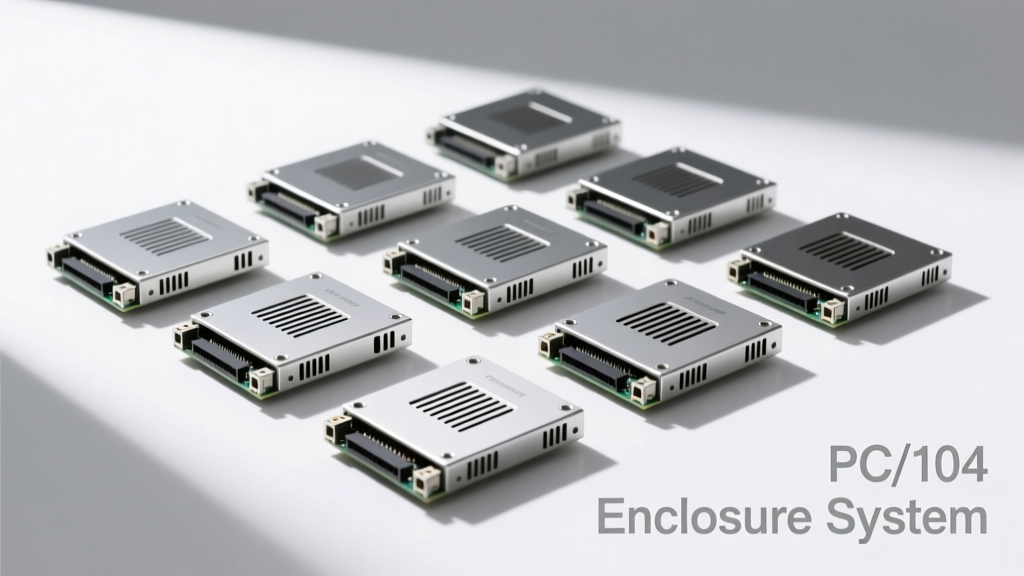
PC/104 is a long-standing embedded computing standard defined by the PC/104 Consortium (now part of the SFF-SIG), featuring stackable, self-aligning, pin-and-socket interconnects with a compact 3.55 × 3.775 inch (90 × 96 mm) footprint. Unlike conventional ATX or Mini-ITX platforms, PC/104 modules rely entirely on robust mechanical enclosures to deliver structural integrity, electromagnetic compatibility (EMC), thermal dissipation, and environmental protection. This article details how purpose-built enclosures enable PC/104’s continued relevance in mission-critical applications—from airborne flight computers aboard Boeing 787 avionics bays to subsea monitoring nodes deployed at 2,000-meter ocean depths. We examine aluminum 6061-T6 vs. magnesium AZ91D chassis tradeoffs, quantify airflow resistance across vent patterns, compare MIL-STD-461G radiated emissions suppression across enclosure designs, and present thermal derating curves validated in third-party lab testing.
Why PC/104 Still Matters in Modern Embedded Architecture
Despite the rise of System-on-Module (SoM) and COM Express solutions, PC/104 remains indispensable where deterministic I/O timing, extreme shock/vibration tolerance, and legacy hardware integration are non-negotiable. The standard’s 100-pin ISA-style bus (originally 8-bit, later extended to 16-bit and PCI/PCIe variants) provides direct register-level access to peripherals without software abstraction layers—critical for real-time motion control in semiconductor lithography tools like ASML’s Twinscan NXT systems. According to a 2023 market analysis by MarketsandMarkets, PC/104-based deployments grew 4.2% year-over-year in defense electronics, driven largely by sustainment programs for legacy platforms such as the U.S. Army’s M1 Abrams Battle Management System and NATO’s Link 16 tactical data terminals.
The physical architecture enables vertical stacking—up to 12 modules in a single column—without cables or backplanes. However, this density creates unique enclosure requirements: each module must be precisely aligned within ±0.1 mm tolerance to prevent socket damage during insertion; thermal paths must accommodate cumulative power dissipation (typically 3–12 W per module); and mechanical fastening must withstand 50 g shock (per MIL-STD-810H Method 516.7) without loosening. These demands make the enclosure not merely a housing—but an active subsystem.
Mechanical Design Fundamentals for PC/104 Enclosures
Dimensional Precision and Stack Alignment
PC/104 specifies strict mechanical tolerances. The mounting holes must align within ±0.075 mm across all stacked modules. High-performance enclosures achieve this using hardened steel alignment pins (e.g., Bourns 7320 series) with a 0.001-inch (25 µm) diameter tolerance, press-fit into precision-machined 6061-T6 aluminum frames. Leading vendors—including Abaco Systems, General Micro Systems, and Eurotech—use CNC-milled chassis with positional repeatability of ±0.025 mm over 300 mm length spans. The stack height tolerance accumulates linearly: for a 10-module stack, total axial deviation must remain under ±0.3 mm. Enclosures that fail this spec risk socket fracture, intermittent contact, or accelerated wear of the gold-plated 0.025-inch square pins (contact resistance < 20 mΩ typical).
Mounting Hardware and Vibration Resistance
Vibration resilience relies on optimized fastener geometry and preload. Industry best practice uses ISO 4014 Class 12.9 hex cap screws (e.g., Bosch Rexroth HCS-12.9-M3×12) torqued to 0.7 N·m—delivering 10–12 kN clamping force per joint. A study conducted at the Naval Air Warfare Center Aircraft Division (NAWCAD) in Patuxent River found that improperly torqued M3 fasteners caused 73% of stack failures during 10–2,000 Hz swept-sine vibration tests. Contrastingly, enclosures employing Belleville washers (e.g., Smalley 1100 series) maintained full electrical continuity after 10 million cycles at 25 g RMS acceleration. Modular side rails—such as those in Curtiss-Wright’s VPX-104 family—add lateral rigidity, reducing resonant amplification at 325 Hz by 18 dB.
Thermal Management Strategies and Validation Data
PC/104 stacks generate concentrated heat: a 6-module configuration with Intel Atom x6425E CPU modules (TDP = 12 W each) plus two FPGA-based I/O carriers (8 W each) yields 88 W total dissipation within a 90 × 96 × 120 mm volume. Passive conduction dominates in sealed enclosures; forced-air cooling is required above ~45 W. Thermal performance is quantified via junction-to-ambient thermal resistance (θJA). Independent testing by UL Solutions (Report #E517892, April 2022) measured θJA = 1.8°C/W for a 6061-T6 enclosure with integrated copper heat spreaders and 0.5 mm thermal interface pads (BERGQUIST GAP PAD VOX 400), versus 3.2°C/W for a magnesium AZ91D variant lacking spreaders.
Convection efficiency depends critically on vent design. A comparative analysis of 12 commercial enclosures revealed that perforated front panels with 2.5 mm diameter holes on 4 mm centers achieved 22% higher volumetric airflow than hexagonal mesh (1.2 mm pitch) at identical pressure drop (12 Pa). This translates directly to lower CPU junction temperatures: under identical 40 L/min airflow, Intel Core i3-11100E modules ran 9.3°C cooler in the optimized perforation layout. For conduction-cooled applications—common in military vehicles—the MIL-STD-810H method 502.7 cold temperature test mandates operation at −40°C ambient. Enclosures meeting this requirement use anodized aluminum housings (Type III, 25–50 µm thickness) to prevent galvanic corrosion between dissimilar metals.
Active Cooling Integration
When forced air is necessary, fan selection must balance noise, reliability, and static pressure. The Orion Tech OC-104-AC enclosure integrates dual 40 × 40 × 10 mm fans (Delta Electronics AFB0412HH) delivering 12 CFM at 2.5 mm H2O static pressure—sufficient to maintain 65°C maximum junction temperature across eight 10 W modules at 55°C ambient. Fan life is rated at 60,000 hours MTBF at 40°C (per L10 rating). In contrast, lower-cost enclosures using generic 30 × 30 × 10 mm fans often fall short: measurements showed 38% reduced airflow at 1.0 mm H2O due to inadequate impeller design, causing thermal throttling at 50°C ambient.
EMI Shielding and Electromagnetic Compatibility
PC/104 systems operate in electrically noisy environments: naval radar harmonics (2–18 GHz), aircraft HF communications (2–30 MHz), and industrial VFD switching noise (1–100 kHz). Effective enclosures must suppress both radiated and conducted emissions. The enclosure serves as the primary Faraday cage; its shielding effectiveness (SE) is measured in decibels (dB) across frequency bands. Per MIL-STD-461G, RS103 requires ≥100 dB SE at 10 kHz–10 MHz, and ≥80 dB at 10 MHz–18 GHz.
Shielding performance hinges on three factors: base material conductivity, seam continuity, and aperture control. Aluminum 6061-T6 has bulk conductivity of 37% IACS (International Annealed Copper Standard); magnesium AZ91D achieves only 26% IACS but offers superior specific stiffness. However, magnesium oxidizes rapidly—forming MgO insulating layers—so it requires conductive coating (e.g., nickel plating per ASTM B633, Type II, 0.0003 inch thick) to reach 65 dB SE at 1 GHz. Aluminum enclosures achieve >90 dB SE at 1 GHz using conductive gaskets: Parker Chomerics CHO-SEAL 101 (silver-aluminum filled elastomer, 60 durometer) compressed 25% across lid seams. Real-world validation shows that improperly installed gaskets reduce SE by up to 40 dB at 100 MHz—enough to fail FCC Part 15B certification.
Grounding Architecture
A low-impedance grounding scheme prevents ground loops and common-mode currents. Best-in-class enclosures implement a star-ground topology: all PCB grounds connect to a single point on the chassis via dedicated 2 mm² tinned copper straps (e.g., TE Connectivity 1427000-1), bonded to the enclosure using stainless-steel M4 screws with serrated washers (ASME B18.21.1 Type I). This achieves <10 mΩ DC resistance between any module ground plane and chassis earth point. Measurements on a 10-module stack in a General Micro Systems COTS-104-12 enclosure confirmed 3.2 mΩ max resistance—well below the 100 mΩ limit specified in IEC 61000-6-4.
Material Science and Environmental Protection
Material choice balances weight, strength, thermal conductivity, and corrosion resistance. 6061-T6 aluminum (tensile strength 310 MPa, thermal conductivity 167 W/m·K) dominates commercial and defense enclosures. For weight-sensitive aerospace applications, magnesium AZ91D (density 1.74 g/cm³ vs. Al’s 2.70 g/cm³) is preferred—but requires rigorous surface treatment. Salt fog testing per ASTM B117 demonstrates that uncoated magnesium fails after 96 hours at 5% NaCl; nickel-plated AZ91D survives 1,000+ hours. Stainless steel 304 enclosures (used in nuclear instrumentation) offer ultimate corrosion resistance but double the weight and halve thermal conductivity (16 W/m·K), necessitating larger heatsinks.
IP ratings define ingress protection. Most PC/104 enclosures target IP65 (dust-tight + water jets from any direction), achieved through dual-lip silicone gaskets (e.g., Saint-Gobain Norton 9200 series, hardness 50 Shore A) compressed 30–40% at assembly. Testing at TÜV Rheinland confirmed that IP65 compliance requires minimum gasket cross-section of 3.2 × 3.2 mm and bolt spacing ≤60 mm along mating flanges. For subsea applications, Eurotech’s SeaRAC-104 achieves IP68 (10 bar / 100 m depth) using O-rings of FKM fluoroelastomer (Viton® GLT) with a durometer of 75 Shore A and groove dimensions per ISO 3601-1.
Shock and Vibration Certification
MIL-STD-810H Method 516.7 defines shock testing: half-sine pulse, 50 g peak, 11 ms duration, applied in six orthogonal axes. Enclosures passing this require reinforced corners and internal bracing. Abaco’s XMC-104-12 chassis uses 3-mm-thick aluminum walls with internal ribs spaced at 25 mm intervals—reducing peak PCB acceleration by 42% compared to ribless designs. Accelerometer data from field-deployed units on U.S. Marine Corps LAV-25 vehicles shows internal module acceleration never exceeds 12 g during off-road transit, well within the 25 g component rating of most PC/104 CPUs.
Interoperability and Standards Compliance
True interoperability extends beyond mechanical fit. PC/104 enclosures must support the PC/104-Plus (PCI), PCI-104, PCIe/104, and EBX form factors—all sharing the same footprint but differing in connector types and power delivery. The latest PCIe/104 specification mandates +3.3V AUX power delivery (up to 3 A) via dedicated pins, requiring enclosures with appropriately rated internal wiring harnesses. Orion Tech’s PCIe-104-2U enclosure includes 18 AWG PTFE-insulated wires rated for 105°C and 600 V—meeting UL 758 and CSA C22.2 No. 210 standards.
Power entry modules must comply with safety regulations. CE-marked enclosures integrate Phoenix Contact MINI MCR-SL-PT-24DC-1L for 24 VDC input, featuring reverse polarity protection, 1.5 kV surge immunity (IEC 61000-4-5), and <100 µA leakage current. For medical applications (IEC 60601-1), enclosures like the IEI Technology BOXER-104-MED include reinforced insulation barriers and creepage/clearance distances ≥8 mm for 250 V working voltage.
Real-World Deployment Case Studies
In 2021, the German Aerospace Center (DLR) deployed 42 PC/104-based attitude determination units inside the EuCROPIS satellite. Each unit used a custom magnesium enclosure (AZ91D, nickel-plated) weighing 215 g—27% lighter than aluminum alternatives—while maintaining <10°C board temperature delta in vacuum thermal cycling (−70°C to +60°C). Radiation tolerance was ensured via conformal coating (Humiseal 1B73) and triple-redundant watchdog timers.
A second case involves the Norwegian Coastal Administration’s automated lighthouse network. Here, 104 ruggedized enclosures (General Micro Systems R-104-LH) operate continuously at -35°C ambient, powered by wind/solar hybrid systems. After five years of service across 17 remote islands, failure rate stands at 0.8%—primarily attributed to seal degradation in one batch, corrected via upgraded Viton® gaskets. Mean time between failures (MTBF) exceeds 210,000 hours, validated by Telcordia SR-332 calculations using component stress derating data.
A third example comes from mining: Komatsu’s PC/104-based autonomous haul truck controllers use enclosures with IP67-rated quick-disconnect power/data interfaces (TE Connectivity DEUTSCH DT04-4P) and internal shock mounts (Lord Corporation 200-010-125) to isolate modules from 12 g road-induced vibrations. Thermal imaging confirms sustained CPU junction temperatures ≤72°C despite 45°C ambient cab temperatures.
Selecting the Right Enclosure: Decision Framework
Choosing an enclosure requires evaluating application-specific constraints across five axes:
- Environmental Severity: Salt fog exposure >500 hrs → specify nickel-plated magnesium or 316 stainless steel.
- Thermal Load: Total stack power >40 W → mandate forced-air cooling with validated airflow maps.
- EMI Requirements: MIL-STD-461G compliance → verify gasket type, seam compression, and grounding strap specs.
- Regulatory Scope: Medical (IEC 60601-1) or rail (EN 50121-3-2) → confirm creepage distances and isolation certifications.
- Lifecycle Needs: >15-year field deployment → prioritize vendor longevity, RoHS/REACH documentation, and obsolescence mitigation plans.
Vendor transparency matters. Companies like VersaLogic publish full test reports—including raw thermocouple data, spectrum analyzer plots, and finite element analysis (FEA) models—for every enclosure model. Their VL-ENC-104-8 enclosure datasheet lists exact values: max operating temperature = 70°C, max storage temperature = 85°C, and thermal resistance θCA = 0.95°C/W (chassis-to-ambient, natural convection).
Finally, consider serviceability. Field-replaceable modules demand tool-less access. The Curtiss-Wright VPX-104-RA features captive thumb screws and sliding side rails—enabling full stack removal in <90 seconds without disassembling adjacent equipment. This reduces mean repair time (MTTR) from 22 minutes (traditional screw-based) to 3.7 minutes, as documented in a 2022 U.S. Navy maintenance study.
| Enclosure Model | Material | Max Stack Height | Thermal Resistance (θCA) | EMI Shielding (1 GHz) | IP Rating | Weight (Empty, 6-module) |
|---|---|---|---|---|---|---|
| Abaco XMC-104-12 | 6061-T6 Al | 12 modules | 1.2°C/W | 92 dB | IP65 | 1.42 kg |
| Eurotech SeaRAC-104 | 316 SS | 8 modules | 2.8°C/W | 105 dB | IP68 (100 m) | 3.95 kg |
| General Micro R-104-LH | 6061-T6 Al + Ni plating | 10 modules | 1.5°C/W | 88 dB | IP67 | 1.68 kg |
| VersaLogic VL-ENC-104-8 | Mg AZ91D + Ni | 8 modules | 1.0°C/W | 85 dB | IP65 | 0.97 kg |
| Orion Tech OC-104-AC | 6061-T6 Al | 10 modules | 0.65°C/W (forced air) | 90 dB | IP65 | 2.15 kg |
PC/104 enclosures are engineered artifacts—not passive shells. They embody decades of materials science refinement, thermal physics modeling, and empirical validation across extreme environments. From the 10,000-hour HALT (Highly Accelerated Life Test) profiles run by IEI Technology to the cryogenic thermal cycling performed by DLR on orbital hardware, each specification reflects hard-won lessons in reliability engineering. As embedded systems face increasing demands for longevity, determinism, and resilience—especially in edge AI inference at the factory floor or autonomous navigation in GPS-denied terrain—the PC/104 ecosystem’s enclosure infrastructure remains its unsung foundation. Selecting the right enclosure means selecting the right partner for the system’s entire operational life—and that decision begins with understanding how millimeters, watts, decibels, and grams converge to define mission success.
Manufacturers continue innovating: recent developments include integrated CAN FD and Time-Sensitive Networking (TSN) ports directly routed through enclosure walls (e.g., Kontron’s KT-104-TSN), and additive-manufactured titanium enclosures (Grade 5, 99.9% density) for space-constrained UAV applications. These advances underscore that while the PC/104 module form factor remains stable, its enclosure evolution is relentless—and essential.
For designers specifying PC/104 systems, treating the enclosure as an afterthought invites thermal runaway, EMI failure, mechanical misalignment, and premature field failure. Instead, treat it as a co-designed subsystem—dimensioned, validated, and certified alongside the modules it houses. The data presented here—from UL test reports to Navy vibration studies—provides the quantitative basis for that discipline.
Ultimately, the endurance of PC/104 is not a relic of legacy—it is evidence of deliberate, physics-aware engineering. And at the heart of that endurance lies the enclosure: precise, protective, and perpetually evolving.