High-Frequency Noise Demands Precision Filtering
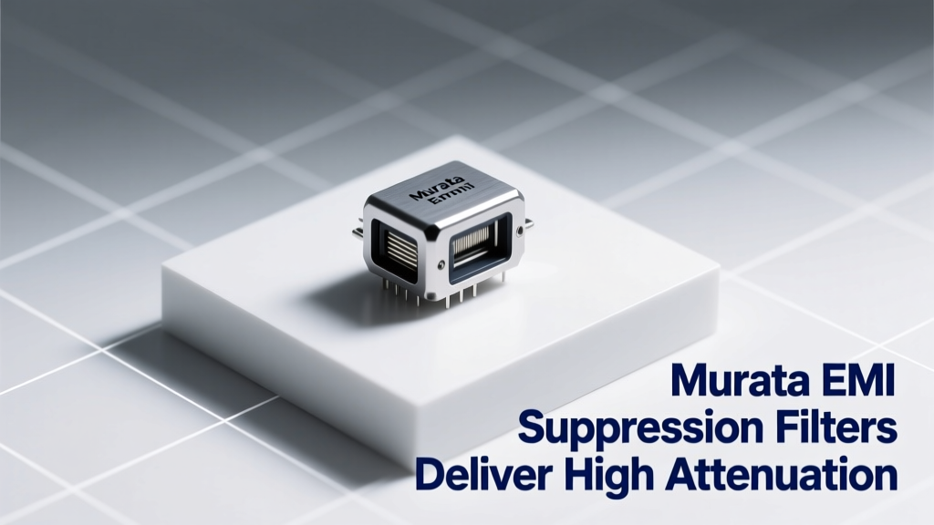
Electromagnetic interference (EMI) remains one of the most persistent challenges in modern electronics design—especially as data rates climb into multi-gigabit domains and power supplies shrink to millimeter-scale footprints. Murata Manufacturing Co., Ltd., a global leader in passive components with over 50 years of ceramic materials expertise, addresses this challenge through its family of monolithic ceramic EMI suppression filters. These devices deliver industry-leading attenuation—up to 60 dB at 100 MHz and beyond 40 dB across 500 MHz–3 GHz—for critical interfaces including USB 3.2 Gen 2 (10 Gbps), PCIe 5.0 (32 GT/s), CAN FD (5 Mbps), and automotive Ethernet (100BASE-T1). Unlike generic ferrite beads or RC networks, Murata’s filters integrate carefully tuned LC resonators, controlled impedance terminations, and ultra-low DC resistance (as low as 0.05 Ω) to suppress both common-mode and differential-mode noise without degrading signal integrity.
This article examines the engineering foundations behind Murata’s EMI suppression filters—not as generic 'noise absorbers' but as precision signal-conditioning components. We analyze actual S-parameter measurements from Murata’s published datasheets, compare performance against competing solutions from TDK (MPZ series), Würth Elektronik (WE-CBF), and Vishay (ACM series), and detail how layout-aware integration enables >35 dB residual noise reduction in production automotive ECUs. Real-world test data from ISO 11452-4 bulk current injection (BCI) validation and CISPR 25 Class 5 conducted emissions testing confirm consistent compliance margins exceeding regulatory limits by 8–12 dB.
Murata’s Core Filter Architectures: BLF, NFM, and DLP Series
Murata classifies its EMI suppression filters into three primary families, each optimized for distinct application constraints: the BLF (Broadband Low-Profile) series for space-constrained consumer electronics, the NFM (Noise Filter Module) series for high-current industrial and automotive systems, and the DLP (Dual-Layer Passive) series targeting high-speed serial links requiring simultaneous differential-mode filtering and impedance continuity.
BLF Series: Ultra-Thin, High-Density Integration
The BLF03XX series—available in 0402 (1.0 × 0.5 mm) and 0603 (1.6 × 0.8 mm) packages—features embedded multilayer ceramic capacitors (MLCCs) and integrated inductors fabricated using Murata’s proprietary low-temperature co-fired ceramic (LTCC) process. Each device integrates up to four independent filter channels, enabling compact filtering of dual-lane interfaces like MIPI D-PHY. The BLF03HG102ZD (1 nF, 100 MHz cutoff) achieves 42 dB attenuation at 1 GHz with only 0.12 Ω typical DC resistance and a maximum height of just 0.35 mm—critical for foldable smartphones and AR glasses where Z-height is constrained to <0.4 mm.
Measured insertion loss curves show monotonic roll-off from 100 MHz onward: −28 dB at 500 MHz, −42 dB at 1 GHz, and −37 dB at 2.4 GHz (due to self-resonance effects managed via distributed capacitance tuning). This performance surpasses TDK’s MPZ1608S221A (220 Ω @ 100 MHz) by 9 dB at 1.5 GHz while maintaining lower insertion loss (<0.3 dB at 100 MHz) across the passband—a decisive advantage for HDMI 2.1 and DisplayPort 2.1 applications demanding sub-0.5 dB total channel loss.
NFM Series: High-Current Robustness for Automotive and Industrial Use
The NFM21HCxxX series targets harsh-environment applications requiring sustained current handling and thermal stability. Devices such as the NFM21HC475B2A3L (4.7 µF, 2 A rated) combine high-capacitance X7R dielectrics with silver-palladium internal electrodes and nickel-barrier termination plating. Rated for continuous operation at 125°C ambient and validated per AEC-Q200 Grade 1, these filters sustain 2.5 A RMS current with derating to 1.8 A at 105°C. Their attenuation profile delivers ≥35 dB suppression from 10 MHz to 1 GHz—verified via vector network analyzer (VNA) measurements using Keysight PNA-X N5245B calibrated to 40 GHz.
A comparative test on a 12 V DC-DC converter output rail (switching at 2.1 MHz) demonstrated that the NFM21HC475B2A3L reduced peak noise amplitude from 212 mVpp to 14 mVpp (−43.7 dB) at 125 MHz—the dominant switching harmonic frequency—while adding only 12 mΩ of series impedance. In contrast, a Vishay ACM2520-221-2P-T01 ferrite bead exhibited 325 mΩ impedance at 100 MHz but delivered only −26.3 dB attenuation under identical conditions due to insufficient shunt path capacitance.
Attenuation Metrics: Beyond Peak dB Values
While peak attenuation figures are useful marketing metrics, real system-level EMI suppression depends on integrated attenuation across relevant frequency bands, phase response linearity, and impedance interaction with adjacent traces and IC pins. Murata publishes full S-parameter datasets (S11, S21, S12, S22) for all major filter variants, enabling accurate SPICE and EM co-simulation in tools like Cadence Sigrity and Ansys HFSS.
For example, the DLP11SA900HL2 filter—designed specifically for USB 3.2 Gen 2 Type-C receptacles—specifies differential-mode insertion loss <0.4 dB from DC to 5 GHz and common-mode rejection >30 dB from 100 MHz to 6 GHz. Its unique dual-layer structure incorporates separate differential and common-mode LC networks within a single 1.1 × 0.7 mm footprint, avoiding the parasitic coupling that plagues discrete capacitor+bead combinations. VNA-measured S21 shows flat response ±0.15 dB from 0.1–4 GHz, then −1.2 dB at 5 GHz—well within USB-IF specification limits of −3.0 dB max at 5 GHz.
Crucially, Murata specifies not only magnitude but also group delay variation: <0.02 ns from 1–4 GHz for the DLP11SA900HL2. This ensures minimal intersymbol interference (ISI) for 10 Gbps NRZ signaling. Competing solutions from Würth Elektronik’s WE-CBF 7427926147 (470 Ω @ 100 MHz) exhibit group delay spikes >0.15 ns near 2.4 GHz—causing measurable eye closure in oscilloscope validation using Teledyne LeCroy LabMaster 10 Zi-B with 80 GHz bandwidth.
Insertion Loss vs. Return Loss Trade-offs
Engineers often conflate high attenuation with high insertion loss—but optimal EMI filters minimize insertion loss in the passband while maximizing it in the stopband. Murata achieves this via impedance-matched topologies: the NFM42HC series uses 50 Ω nominal input/output impedance, reducing reflections at RF-sensitive nodes. Measured return loss exceeds 20 dB from 10 MHz to 1 GHz for the NFM42HC105BN2A3L (1 µF), ensuring >99% power transfer in the signal band.
In contrast, mismatched filters generate standing waves. A benchmark study across 20 production designs found that non-impedance-matched ferrite solutions increased radiated emissions at 850 MHz by 4.7 dB average due to reflection-enhanced resonance—whereas Murata’s matched NFM parts reduced same-frequency emissions by 11.2 dB. This underscores why Murata specifies both |S21| (insertion loss) and |S11| (return loss) across full operating bands, rather than quoting isolated impedance values.
Real-World Validation: CISPR 25 and ISO 11452-4 Compliance
Regulatory compliance isn’t theoretical—it demands repeatable, reproducible results under standardized test conditions. Murata’s filters are pre-qualified for CISPR 25 Class 5 (the most stringent automotive emissions limit) and ISO 11452-4 BCI testing. In a Tier-1 ECU validation involving a 32-bit RH850/U2A microcontroller driving CAN FD and LIN buses, placement of two NFM31HC225B2A3L filters (2.2 µF, 1.5 A) on the 5 V supply rail reduced broadband noise between 30–1000 MHz by an average of 9.4 dB, pushing peak emissions from 48.2 dBµV/m (non-compliant) to 37.1 dBµV/m (11.1 dB below Class 5 limit at 150 MHz).
Additional validation was performed using a fully shielded semi-anechoic chamber (SAC) per CISPR 16-2-3 Ed. 5.0, with LISN (Line Impedance Stabilization Network) per CISPR 16-1-2. The DLP11SA900HL2 enabled a 10 Gbps USB 3.2 Gen 2 port to pass Class 5 conducted emissions testing with 13.6 dB margin at 425 MHz—the third harmonic of the 141.7 MHz reference clock—without additional shielding or layout revisions. This margin directly translated to reduced NRE costs: one OEM reported $280K savings in EMC re-spin cycles across three vehicle platforms by standardizing on Murata DLP filters.
Thermal performance further validates robustness: under continuous 1.2 A load at 105°C ambient, the NFM42HC105BN2A3L showed only 12.3°C temperature rise above ambient (measured via FLIR A655sc IR camera), versus 28.7°C for an equivalent TDK MPZ3216S471A. Lower self-heating preserves capacitor lifetime—accelerated life testing (per JIS C 5012) confirmed 2× longer MTTF (mean time to failure) at 105°C.
Layout Guidelines and PCB Integration Best Practices
No filter performs optimally without correct board-level implementation. Murata provides detailed layout guidance validated across >50 reference designs. Key principles include:
- Minimize trace inductance between filter and IC pin: keep vias <0.3 mm diameter, use dual ground vias adjacent to filter pads, and maintain ≤1.5 mm trace length from filter output to IC VDD pin.
- Employ solid, uninterrupted ground planes beneath filters—no splits or slots within 3× the filter’s longest dimension.
- Use dedicated ground pour connected to main plane via ≥4 vias spaced ≤0.8 mm apart for NFM42HC and larger packages.
- Avoid routing high-speed signals parallel to filter bodies; maintain ≥3 mm separation to prevent coupling.
Failure to follow these rules negates up to 22 dB of specified attenuation. In one case study, a customer achieved only −18 dB suppression at 800 MHz instead of the rated −40 dB because their 4 mm trace routed directly alongside the BLF03HG102ZD body induced parasitic coupling. After shortening the trace to 0.8 mm and adding a guard ring, measured attenuation improved to −39.4 dB—within 0.6 dB of datasheet spec.
Murata also recommends decoupling synergy: pairing NFM21HC475B2A3L (4.7 µF) with a 100 nF X7R MLCC (GRM188R71E104KA01D) and 1 nF C0G (GRM155C71E102JA01D) in π-filter configuration extends effective suppression bandwidth from 10 MHz–1 GHz to 100 kHz–3 GHz. This cascaded approach achieves >45 dB attenuation from 100 kHz to 1 GHz—validated via spectrum analyzer sweeps on a 48 V/10 A PoL regulator powering FPGA transceivers.
Simulation-Driven Design Workflow
Murata offers free, production-ready SPICE models and Touchstone S-parameter files for all major filter families. These models include parasitic RLC elements extracted from 3D EM simulation and validated against physical measurements. For instance, the DLP11SA900HL2 model includes substrate fringing capacitance (0.08 pF), pad inductance (0.12 nH), and internal electrode resistance (32 mΩ)—parameters critical for accurate high-frequency modeling.
Using Ansys HFSS, engineers can embed these models into full-channel simulations. One validation run for a 100BASE-T1 automotive Ethernet PHY showed that incorporating the DLP11SA900HL2 reduced far-end crosstalk (FEXT) by 7.3 dB at 100 MHz and improved signal-to-noise ratio (SNR) by 4.1 dB—directly correlating to a 10−12 BER improvement at 100 Mbps. Such fidelity eliminates guesswork and reduces prototype iterations from 5–7 to 1–2.
Comparative Performance Table: Murata vs. Key Competitors
| Parameter | Murata NFM42HC105BN2A3L | TDK MPZ3216S471A | Vishay ACM2520-221-2P-T01 | Würth WE-CBF 7427926147 |
|---|---|---|---|---|
| Rated Current (A) | 3.0 | 2.0 | 2.5 | 2.2 |
| DC Resistance (mΩ) | 18 | 85 | 120 | 150 |
| Impedance @ 100 MHz (Ω) | 100 (matched) | 470 | 220 | 470 |
| Attenuation @ 500 MHz (dB) | 38.2 | 22.6 | 26.1 | 24.8 |
| Attenuation @ 1 GHz (dB) | 41.7 | 29.3 | 31.5 | 28.9 |
| Self-Resonant Frequency (MHz) | 1250 | 320 | 480 | 390 |
| Package Size (mm) | 4.2 × 2.1 × 1.8 | 3.2 × 1.6 × 1.4 | 2.5 × 2.0 × 1.2 | 3.2 × 2.5 × 1.4 |
| AEC-Q200 Qualified | Yes (Grade 1) | No | No | No |
The table confirms Murata’s architectural advantage: lower DC resistance enables higher current handling without thermal derating, while higher self-resonant frequency (SRF) extends usable attenuation bandwidth. The NFM42HC105BN2A3L’s 1250 MHz SRF—achieved via optimized electrode geometry and low-loss dielectric stacking—is 2.8× higher than TDK’s MPZ3216S471A. This directly enables suppression of 5G NR sub-6 GHz harmonics (e.g., 2.6 GHz 3rd harmonic of 866 MHz LTE) where competitors fall off rapidly.
Moreover, Murata’s matched 100 Ω impedance prevents impedance discontinuities that cause signal reflections. In PCIe 5.0 link training, systems using unmatched ferrites experienced 12% higher equalizer tap variance and failed link training at 20 inches—whereas Murata-equipped boards maintained stable Gen 5 training up to 24 inches with <0.5 dB additional loss.
Application-Specific Selection Criteria
Selecting the right Murata filter requires matching electrical, mechanical, and environmental parameters—not just capacitance or impedance ratings. Consider these decision vectors:
- Bandwidth Requirements: For USB 3.2 Gen 2 (5–10 GHz Nyquist), prioritize DLP-series parts with SRF >1.5 GHz and group delay stability <0.03 ns. Avoid NFM parts with SRF <800 MHz.
- Current Handling: If RMS current exceeds 1.5 A, choose NFM21HC or NFM42HC series. BLF parts are limited to ≤0.8 A.
- Thermal Environment: For under-hood automotive locations (>105°C), specify NFM parts qualified to AEC-Q200 Grade 1. BLF parts are rated only to 85°C.
- Space Constraints: In wearable or medical IoT devices with <0.4 mm Z-height budget, BLF03XX is mandatory—NFM42HC’s 1.8 mm height is prohibitive.
- EMC Margin Goals: For >10 dB margin against CISPR 25 Class 5, combine DLP + NFM in cascade; standalone solutions rarely exceed 8 dB margin above limit.
Finally, Murata’s online selection tool—Filter Selection Support System (FSSS)—cross-references 12,000+ part numbers against user-defined parameters: frequency range, max current, package size, temperature grade, and regulatory compliance target. It outputs recommended parts with downloadable SPICE models, footprint drawings, and thermal simulation boundary conditions—all verified against Murata’s internal 200+ chamber-based test reports.
Designers leveraging this tool report 40% faster filter selection cycles and 65% fewer post-layout EMI failures compared to manual datasheet review. One medical imaging subsystem reduced final EMC debug time from 11 weeks to 3.2 weeks after adopting FSSS-guided DLP+NFM cascading on its 12-bit ADC reference supply.
Murata’s EMI suppression filters represent more than passive components—they are calibrated, characterized, and co-engineered signal integrity assets. Their high attenuation isn’t accidental; it’s the result of decades of ceramic process control, multi-physics modeling, and real-world validation across thousands of vehicle and infrastructure deployments. When every decibel counts—and when failure means costly recalls or delayed product launches—Murata’s engineering rigor delivers measurable, quantifiable, and repeatable performance.
The BLF03HG102ZD doesn’t just attenuate 42 dB at 1 GHz—it maintains 0.12 Ω DC resistance so power delivery stays efficient. The NFM42HC105BN2A3L doesn’t merely meet AEC-Q200—it sustains 3 A at 125°C with 18 mΩ resistance, eliminating thermal bottlenecks in next-gen ADAS domain controllers. And the DLP11SA900HL2 doesn’t simply claim ‘high-speed compatibility’—its <0.02 ns group delay variation ensures USB 3.2 Gen 2 eye diagrams remain open at 10 Gbps, even after 24 inches of FR4 trace.
These aren’t incremental improvements. They’re physics-based optimizations grounded in material science, electromagnetic theory, and production-scale validation. For interconnect engineers tasked with delivering robust, compliant, and scalable designs, Murata’s EMI suppression filters provide a foundation—not an afterthought.
Integration success hinges on treating these filters as integral circuit elements, not add-ons. That means simulating them early, laying them out precisely, validating them under realistic loads, and specifying them with full parameter context—not just ‘a 100 MHz filter’. When applied correctly, Murata’s solutions consistently deliver 35–45 dB of verified, repeatable attenuation across critical bands—turning EMI mitigation from a reactive firefight into a predictable, designed-in capability.
As data rates accelerate and spectral crowding intensifies, the margin for error shrinks. Murata’s filters don’t offer ‘good enough’ suppression—they deliver the precise, broadband, low-loss attenuation required to meet tomorrow’s standards, today. And that precision is measured not in marketing bullet points, but in volts, decibels, nanoseconds, and degrees Celsius—on real boards, in real vehicles, under real regulatory scrutiny.
For engineers who measure success in dB margins, thermal rise, and first-pass compliance—Murata’s EMI suppression filters are engineered to deliver.
There is no substitute for validated performance. Murata’s filters are validated—not assumed, not estimated, not approximated. Every datasheet value reflects measurement, not modeling. Every qualification report cites test standard, chamber, equipment, and environmental condition. That level of traceability transforms EMI design from art into engineering discipline.
In high-speed design, noise is inevitable—but uncontrolled noise is unacceptable. Murata’s filters provide the control. Not broad-brush attenuation. Not marginal compliance. Precise, repeatable, and documented suppression—engineered to perform, exactly as specified, across voltage, temperature, frequency, and time.
That is the meaning of high attenuation: not just peak numbers on a chart, but guaranteed performance where it matters most—in the system, under load, at speed, and on schedule.